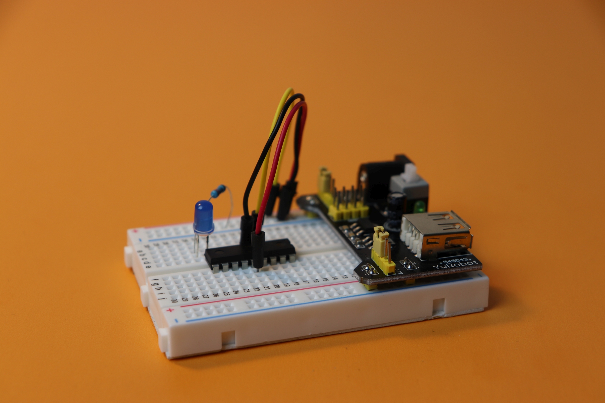
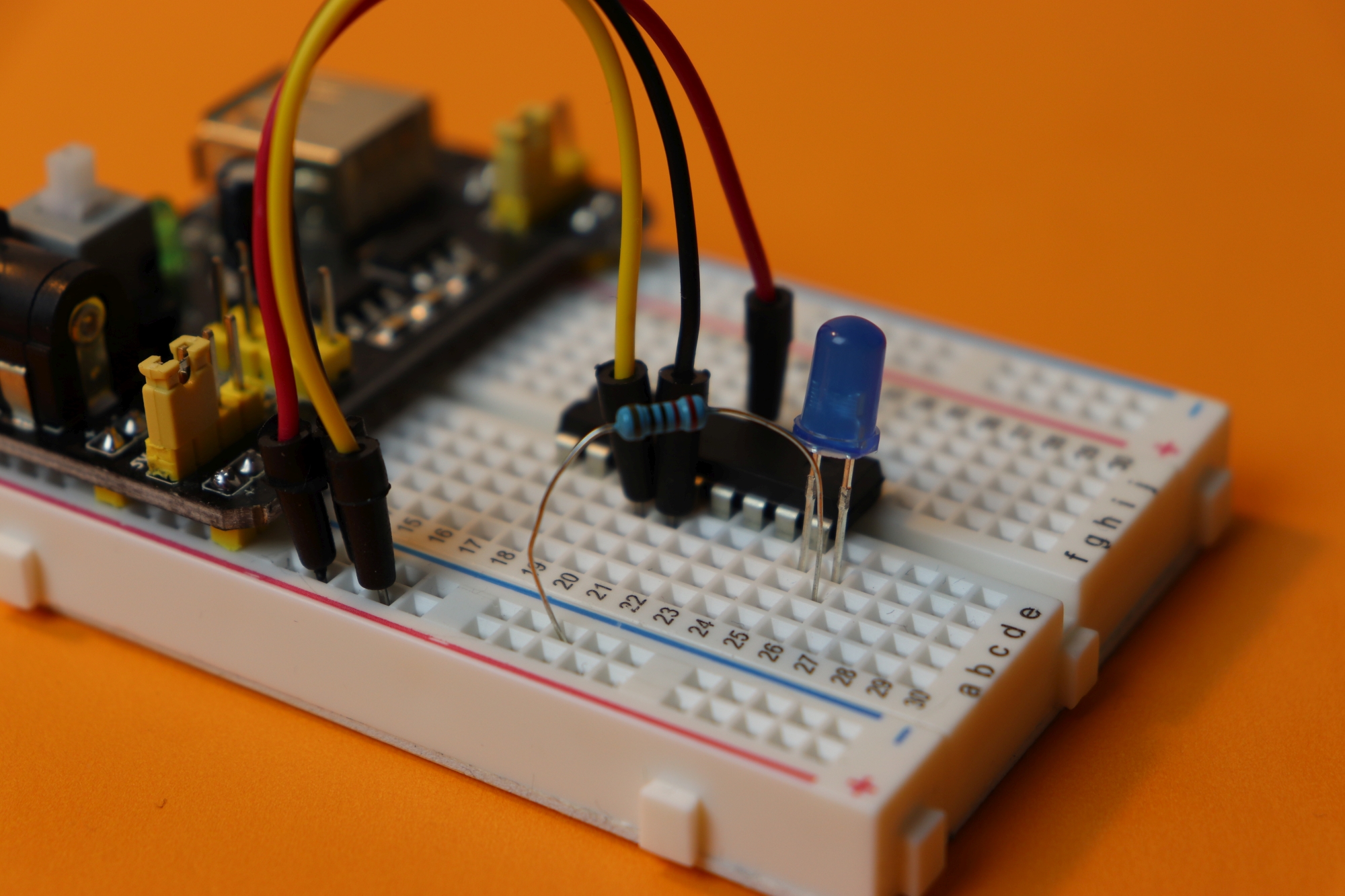
Make an LED blink: your first simple PIC microcontroller project!
April 26, 2019 • tutorial
In the last two weeks we learned how to write our first PIC microcontroller program and how to flash it on to the controller. In this week's post, we will describe the accompanying electronics. Don't worry, it is not very complicated, we will get there!
Step 1: What components do we need?
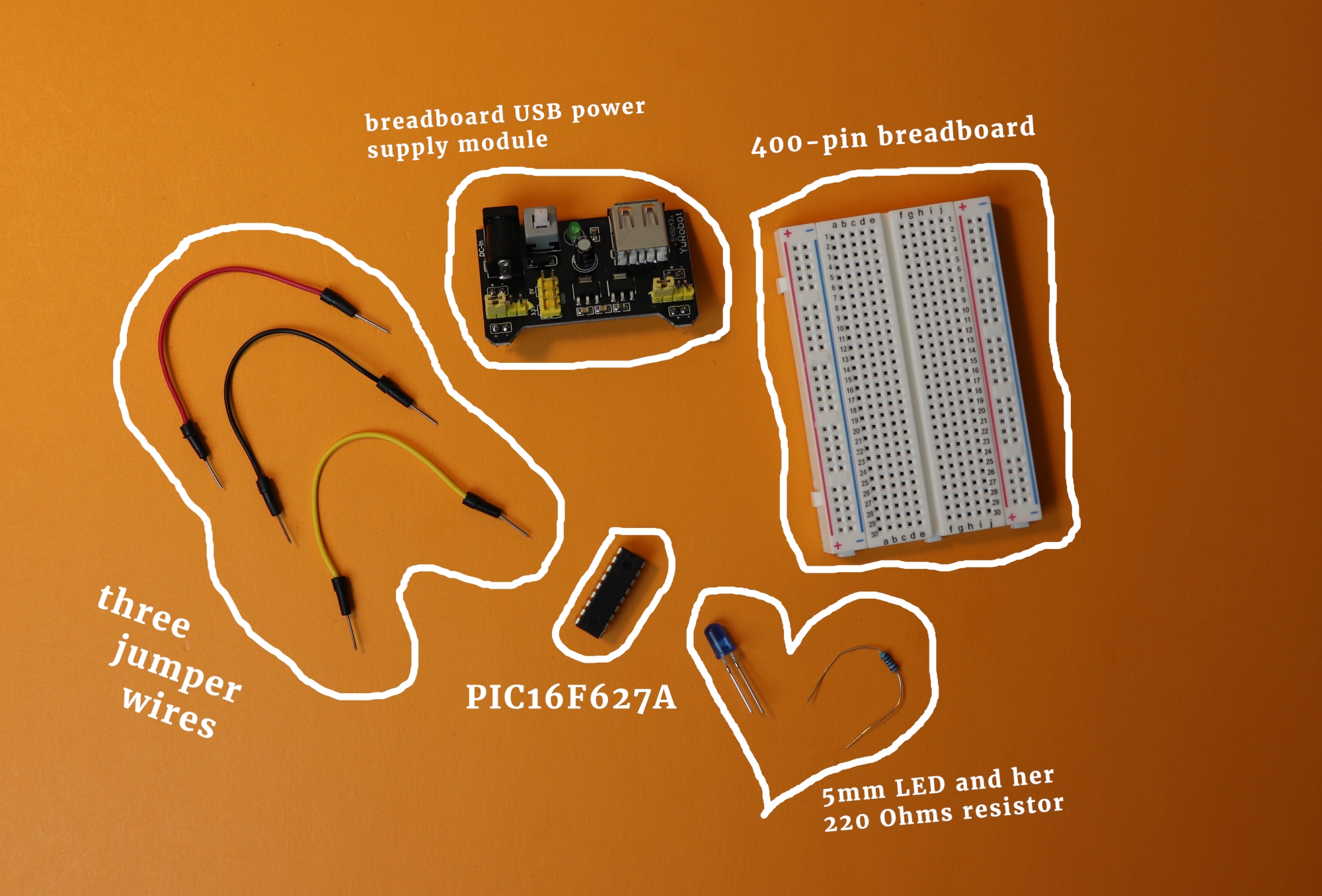
To make it quick and painless, let's just look at what we need:
Alright, that is not too terrible: only eight components! Let's go through, one-by-one:
- The three jumper wires and the 400-pin breadboard are fairly self-explanatory, and they can be bought on Amazon for a few dollars in many many starter kits.
- The breadboard USB power supply module is a personal favorite of mine. It sticks right into the breadboard and supplies +5V (or, if you move the jumpers on it around, also +3.3V) to the two rails on the left and the right of the breadboard. It is not really needed since you can use any other 5V power supply for this project, but I highly recommend getting a few of these. If you buy three or six of them, they only cost a few dollars a piece and they are definitely a good investment if you plan on doing more breadboard experiments :)
- The microcontroller PIC16F627A can be bought for around $2 at many international electronics distributors. I bought mine at Mouser (PIC16F27A here), but you can of course choose what is the most convenient for you.
- Last, we need a standard LED as well as a 220 Ohms resistor. This is not really critical, almost any LED will do. You can find resistor kits and LED kits on Amazon, I put two links in the resources box. A resistor kit is worth the money if you want to do more projects in electronics because it has a wide variety of useful resistor values.
If you wonder where you can purchase these components: I included a few links in the resources box. Of course we also need the PICkit3 and the .hex file, as discussed in the two last posts (post #1, post #2). If that confuses you, maybe now is a good time to go back and read up. If you are confused because I am not making any sense, I encourage you to send me a strongly worded email. :)
Step 2: The schematic
Any good electronics project comes with a schematic. This is the diagram of all the components and it describes how they are connected. I like to use a software called Eagle to draw nice electronics schematics. Eagle is a software that is primarily used for designing printed circuit boards (PCBs), but nobody stops you from using it to draw circuit diagrams or schematics. In fact, it has an ever-growing list of components readily included.
OK, enough chit-chat, here is the schematic:
The schematic is quite simple, and that is very good for a starter project. Let us go through the details, step by step.
- The green-ish lines are the electrical connections between the components, and the components are displayed in red. Each component has a name, and sometimes they also have a value.
- Names: For example, the names of the components in the schematic above are “G1,” “IC1,” “LED1,” and “R1.” You can see that component names are always numbered, and similar components have the same prefix. What do I mean by that? Well, if you have 27 resistors in your schematic they will probably be labeled R1 through R27.
- Values: Each component also may have a value associated with it. In the above schematic, the values are “5V power,” “PIC16F627A,” and “220R.” For a resistor, for example, one needs to know its value. For a simple switch, however, it might not be necessary to provide further details. The same thing is true for our LED. I chose not to put in a value for the LED because it does not matter: it can be red, green, blue, 3mm, 5mm, or 10mm.
-
Non-components: You might have noticed the following symbol in the schematic:

This can be a bit confusing because this symbol is the ground symbol and it does not correspond to a physical component. It is basically just a label. It tells us that all green lines connected to it are identified as the ground potential. The bottom line is: don't worry about it too much. - G1 is our 5V power source. We will use a USB breadboard power supply, but you can use anything you want, as long as it outputs 5V DC.
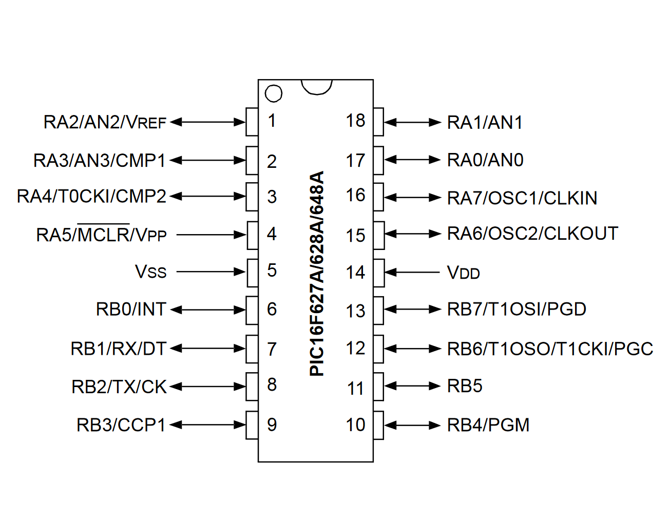
- IC1 is our PIC microcontroller PIC16F627A. It has a total of 18 pins. In the schematic the pins are ordered by function: on the left they increase from RA0 to RA7, and one the right they increase from RB0 to RB7. The PIC16F627A that we are going to stick into the breadboard, in the real world, has 18 pins, that are numbered in a certain way (see more details in the construction). These pin numbers can be seen in the schematic above as well: pin RB3, for example, corresponds to pin 9. The VSS pin, on the other hand, is pin 5. You get the idea :)
- LED1 is the LED that we want to make blink. Its anode is connected to pin RB3. Read more about LEDs in our tutorial here :) If you need a way to remember what the cathode and the anode is, try this: the cathode is the pointy part of the LED in the circuit diagram, because it is a negative thing when you poke yourself at a sharp object. Not sure if it works for you, but for me it was quite helpful!
- Finally, R1 is our resistor. Its value is 220Ω where the “Ω” stands for Ohms. It limits the current that flows to our LED to around 15mA.
That's basically it. Please let me know if I left out something critically important! If you want you can download the Eagle schematic in the resources box :)
Step 3: Construction
Now we have to take the schematic and replicate it on the breadboard. When building it yourself, carefully follow all lines of the schematic and you will be fine.
Just to be safe, the pin numbers on the PIC16F627A microcontroller are also found in the schematic. They are numbered in the following way:
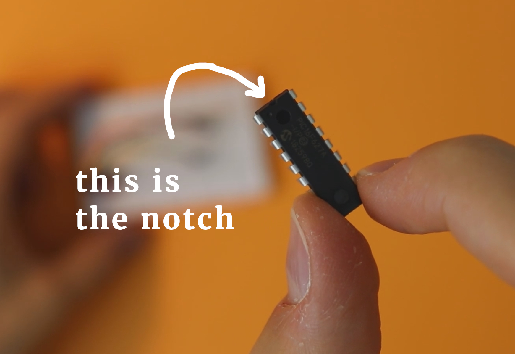
Observe the notch between pins 1 and 18. You have to find this notch on the PIC16F627A in front of you on your table. It is easy to find, but make sure you find it and plug the PIC16F27A in correctly :)
When building this schematic you do not need to know what all these things mean. To be honest, I don't even know what some of these designations stand for. What is important is to understand a few of these. We need to know that we have to connect both MCLR and VDD to +5V, and we need to connect VSS to ground. Also, we need to connect the anode of the LED to pin no. 9 which happens to be called RB3. That's all.
Here is a detailed step-by-step list of instructions (click on the images to open them in an interactive gallery):
-
-
Step 1
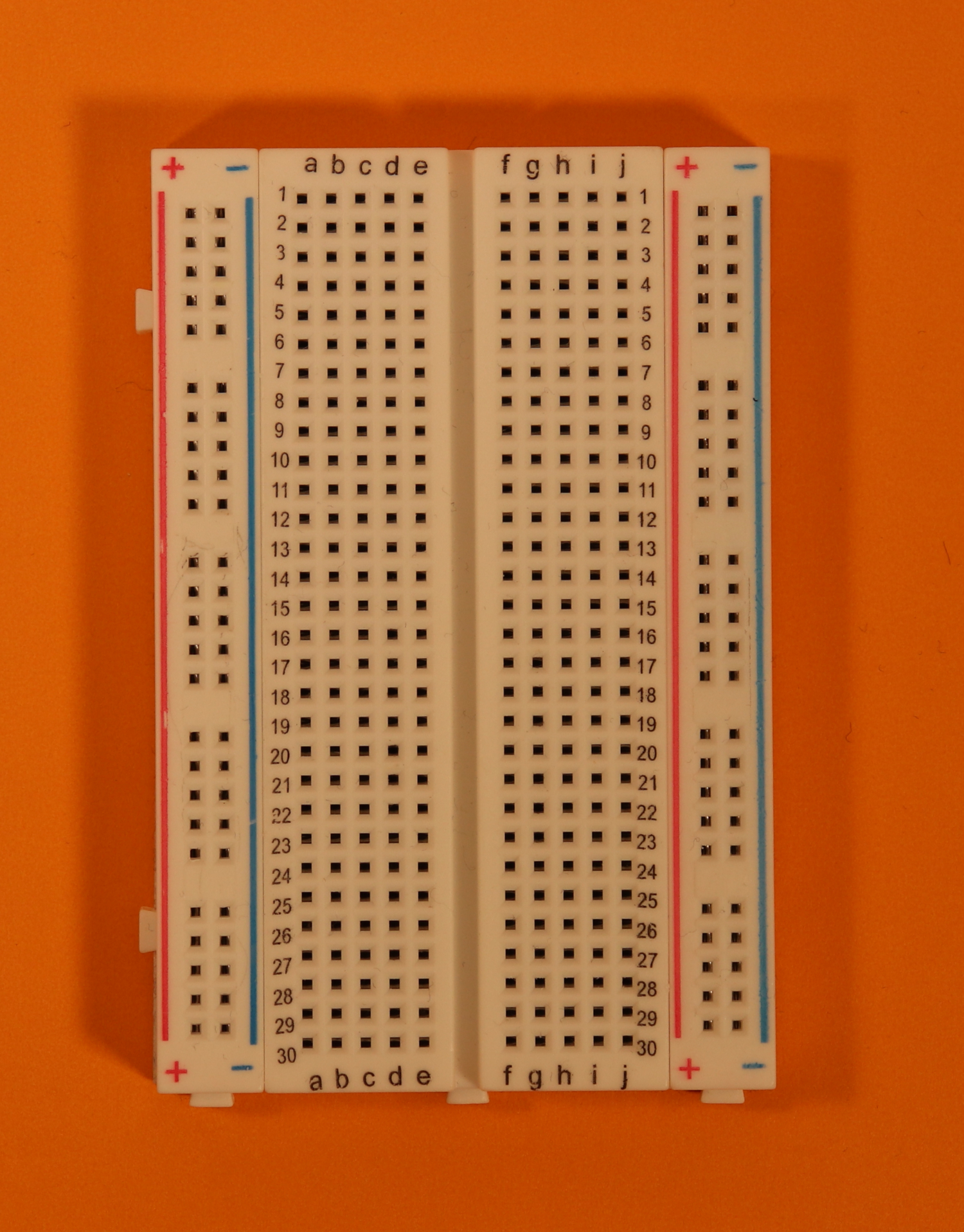
This is your empty breadboard. Place it in front of you with the hole 1a to the top left.
-
-
Step 2
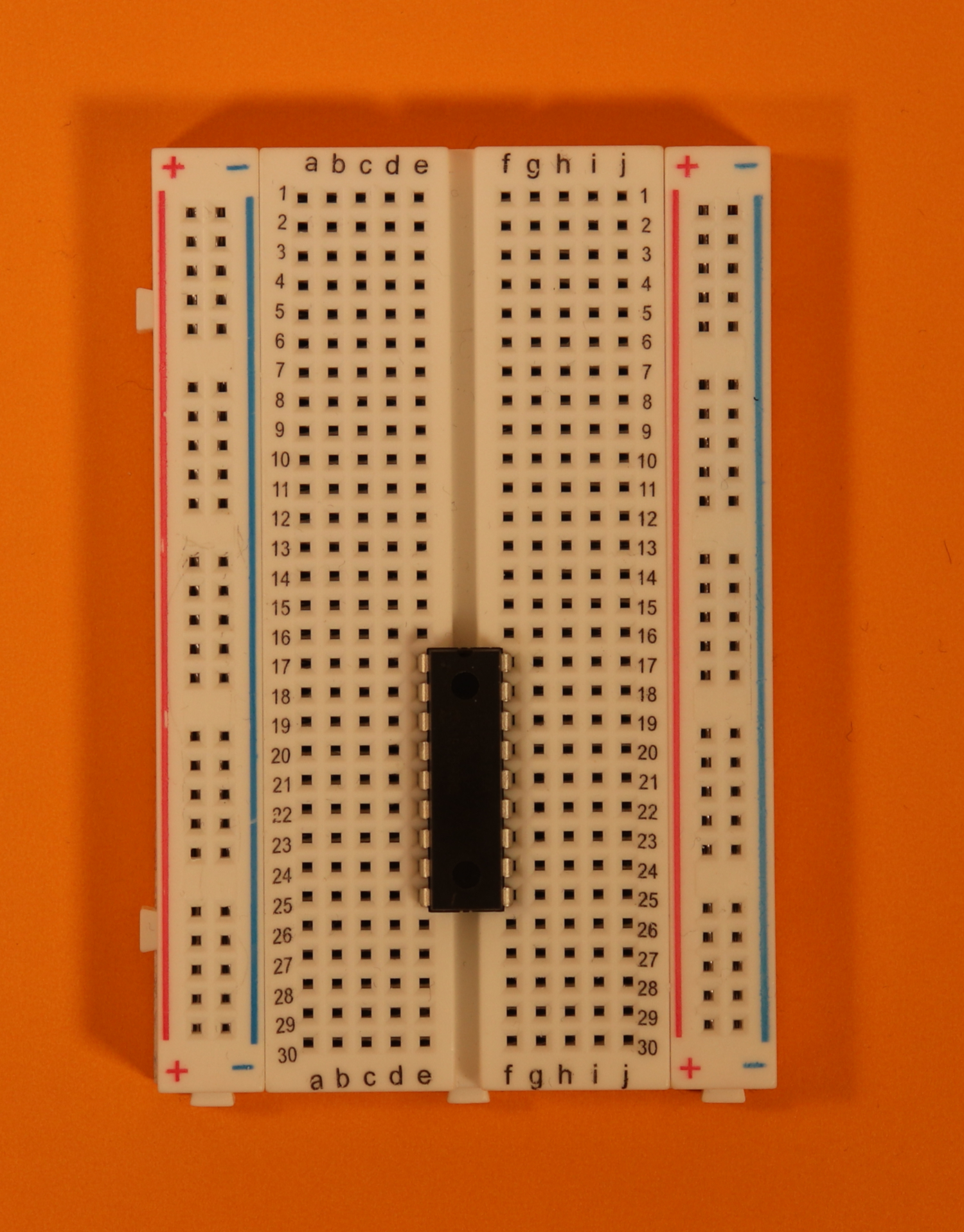
Place the PIC16F627A controller in row 17. Make sure that the notch of the PIC16F627A points up.
See more below under troubleshooting.
Remember that the PIC16F627A on its own is useless! We need to flash it with a hex-file first. You can find a detailed introduction into that topic here :)
-
-
Step 3
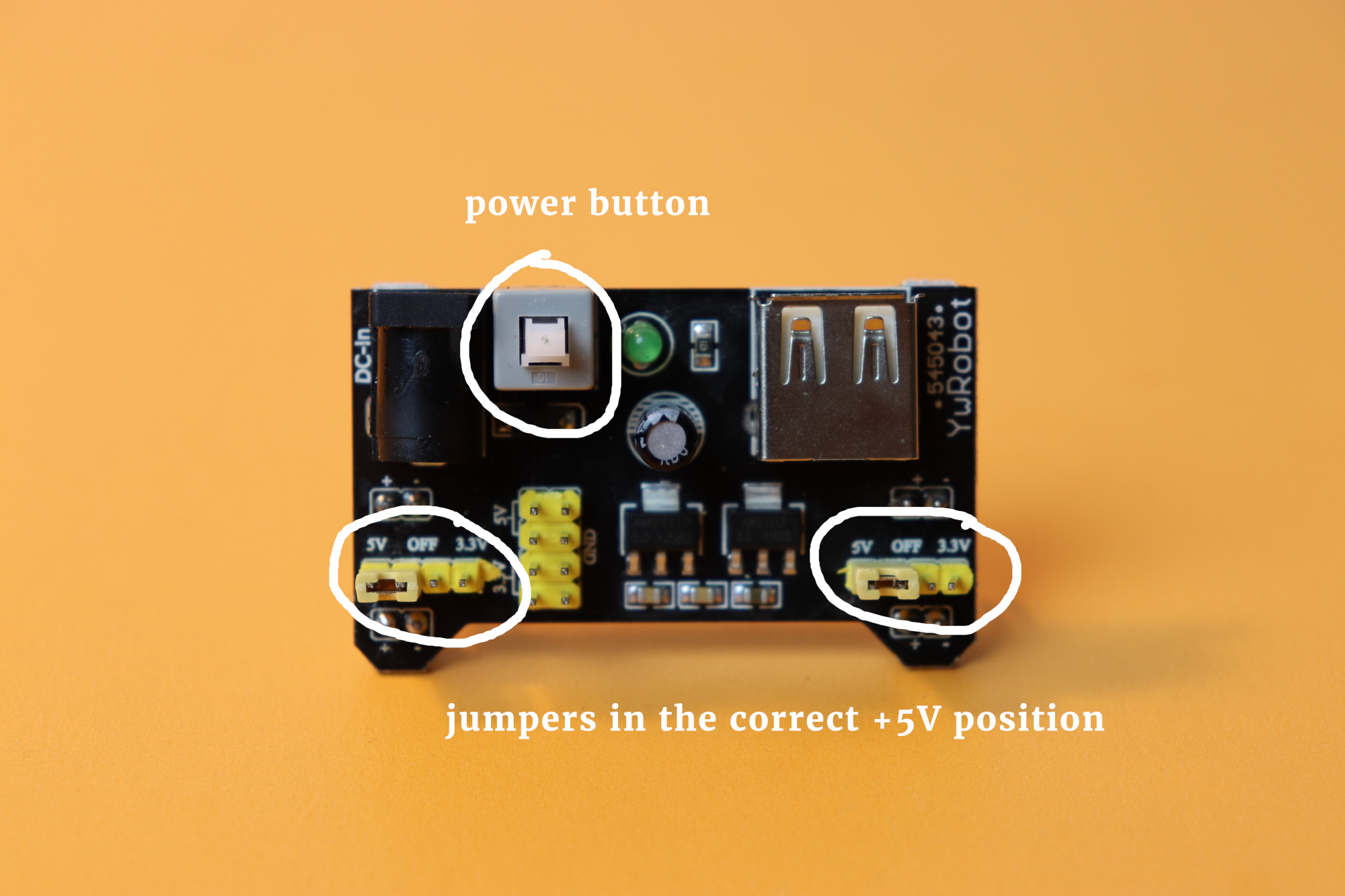
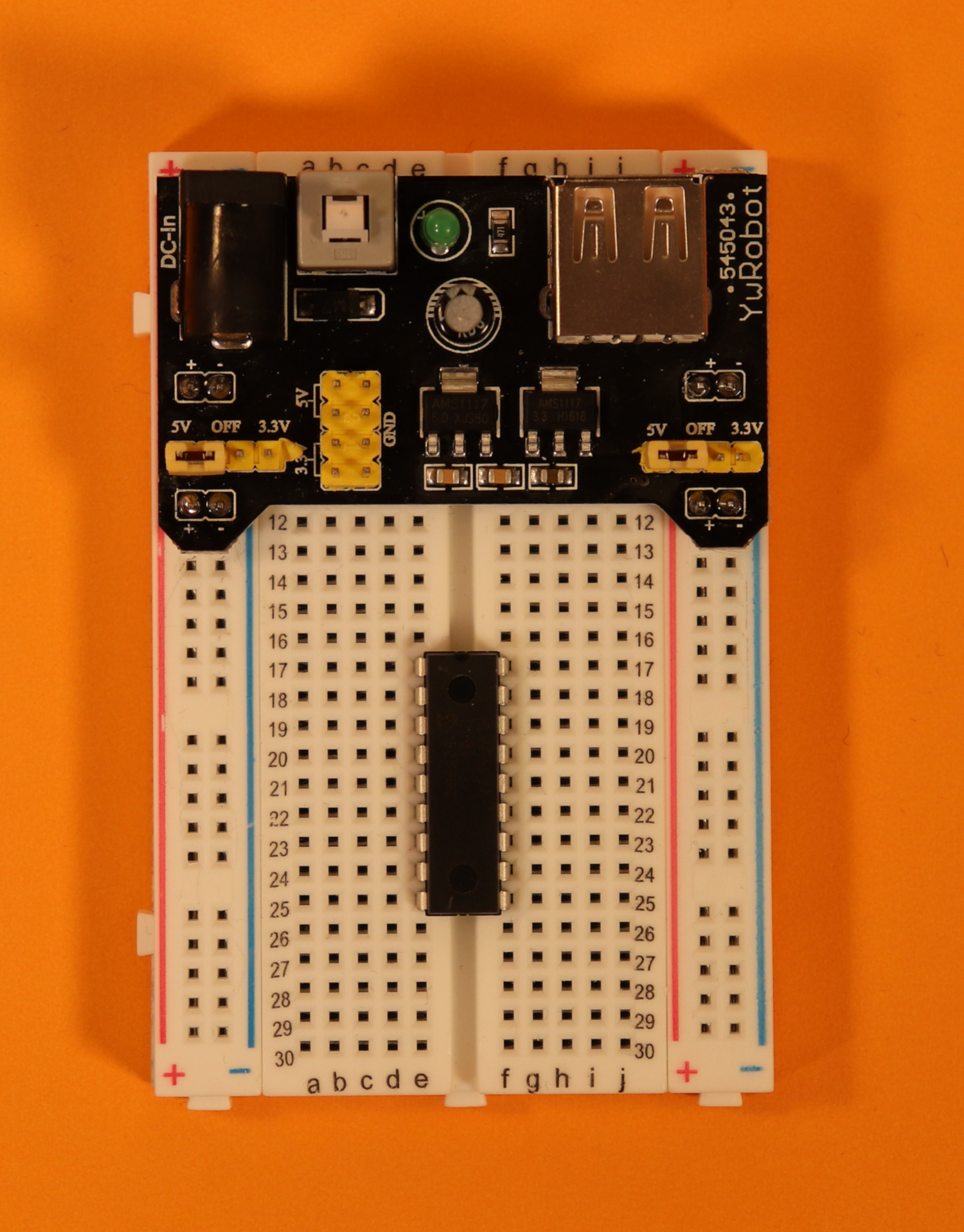
Place the USB breadboard power supply. Make sure that both jumpers are set to the 5V configuration.
See more below under troubleshooting.
-
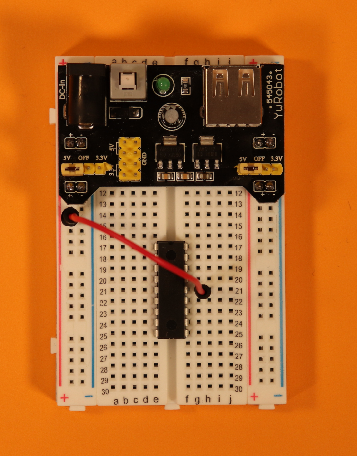
-
Step 4
Use a red cable to connect pin 14 (VDD) of the PIC16F627A with the +5V power rail.
-
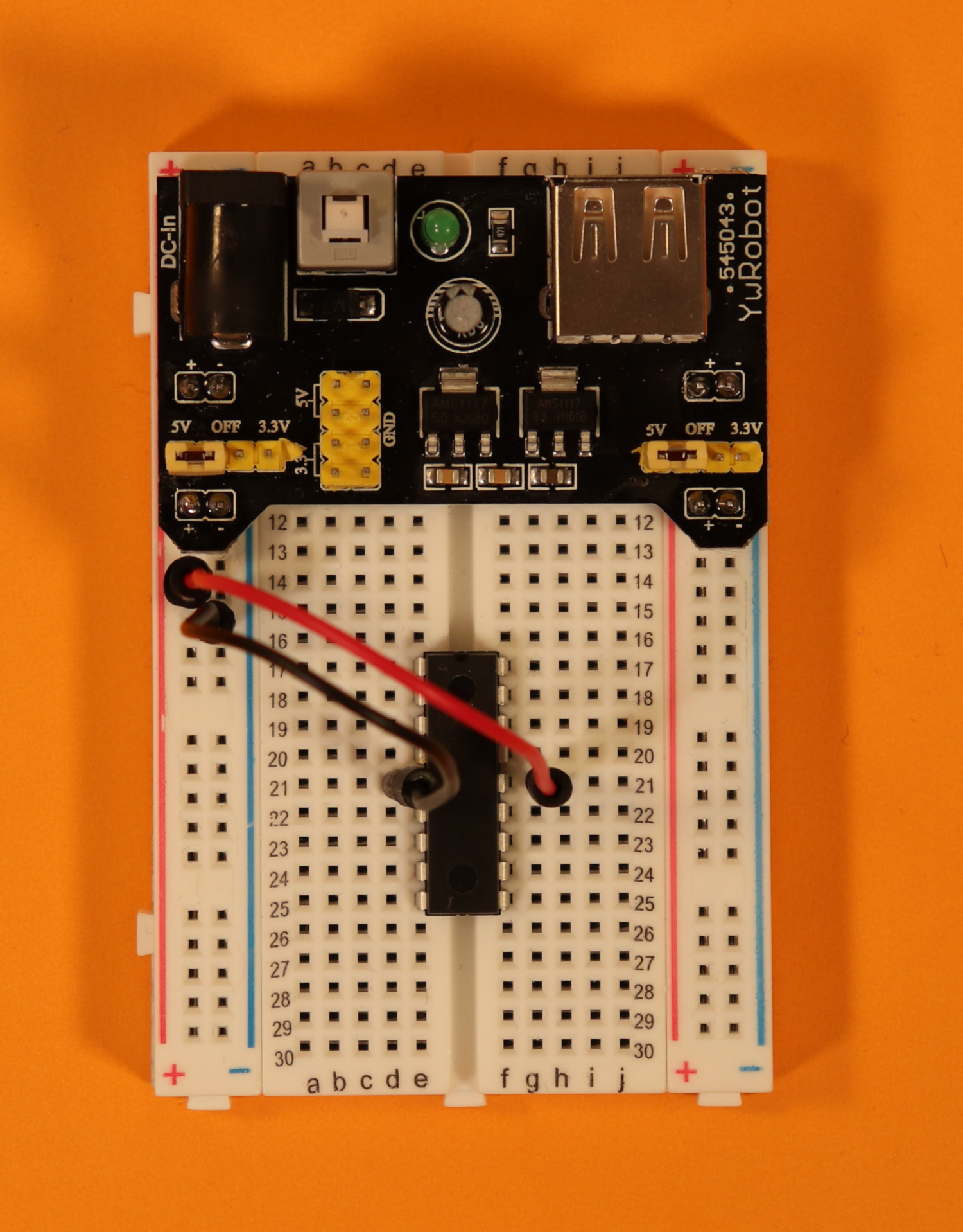
-
Step 5
Use a black cable to connect pin 5 (VSS) of the PIC16F627A with the ground power rail.
-
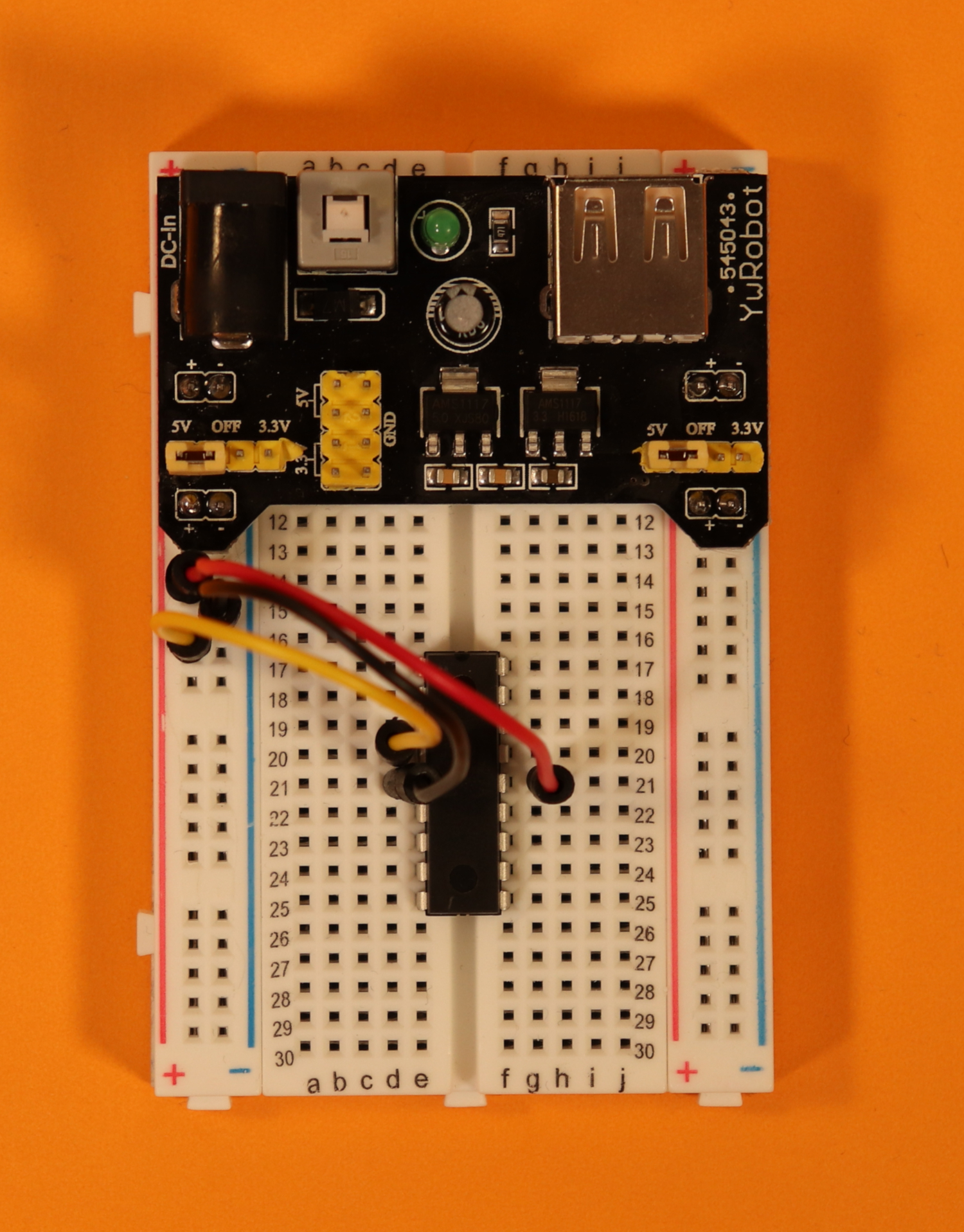
-
Step 6
Use a yellow cable to connect pin 4 (MCLR) of the PIC16F627A with the +5V power rail.
-
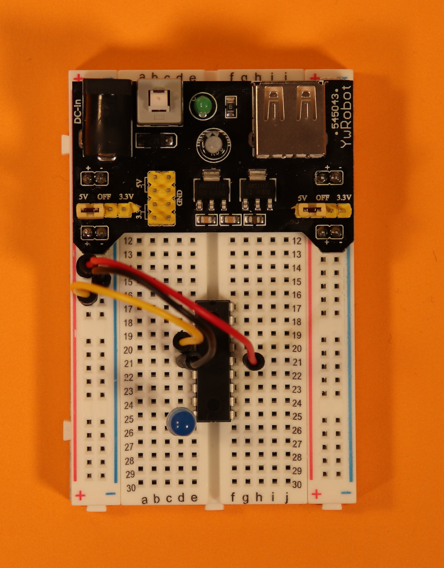
-
Step 7
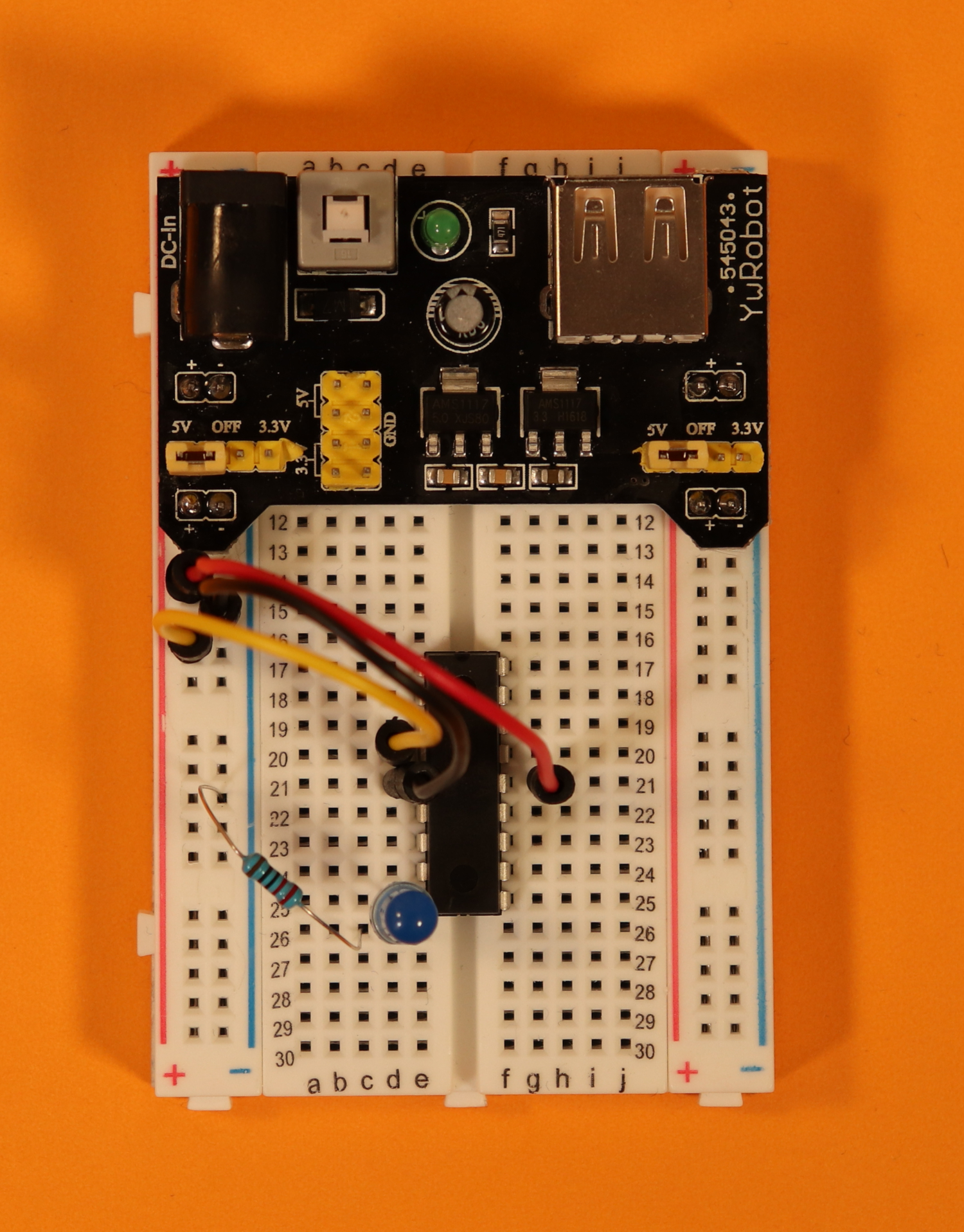
Insert the LED at pin 9 (RB3) of the PIC16F627A. Make sure that the anode is connected to pin 9.
See more below under troubleshooting.
-
-
Step 8
Use a 220Ω resistor to connect the cathode of the LED to the ground power rail.
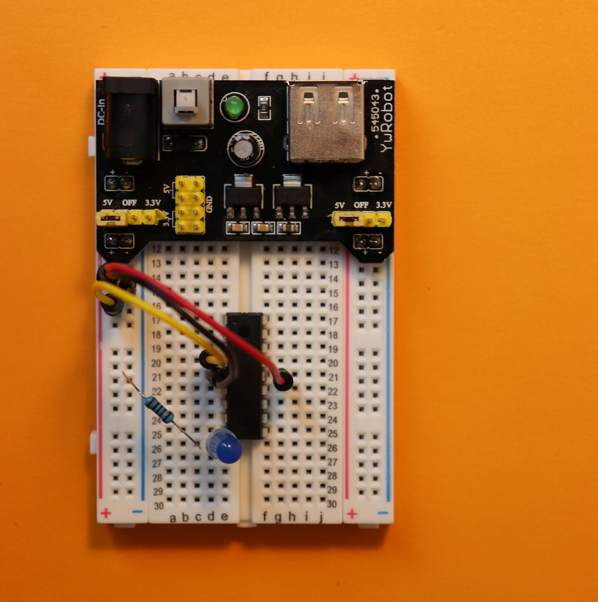
After all is done, you will end up with the final circuit:
Alright, that was fun!
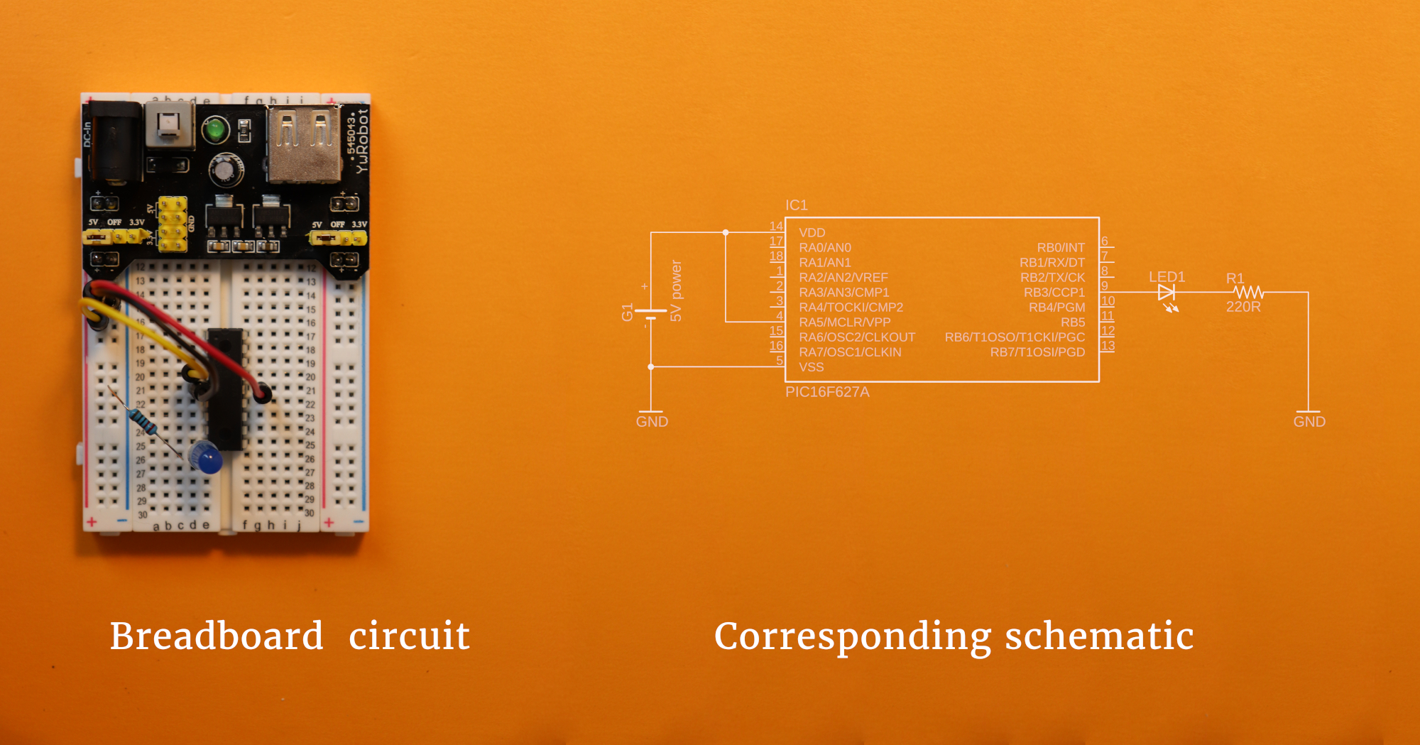
On the left you see the breadboard circuit, all constructed. On the right you see the schematic. It looks quite different, doesn't it? Schematics always come with a certain amount of abstraction, but I am sure you can recognize the main parts that make up the circuit, and how they correspond to the devices in the picture on the left.
Step 4: Power it up!
Now we are ready and we can connect it to power by plugging in a USB cable. Do not forget to switch the power supply on by pressing the grey power button! Also, make sure the power supply jumpers (the tiny yellow thingies) are set to the 5V configuration:
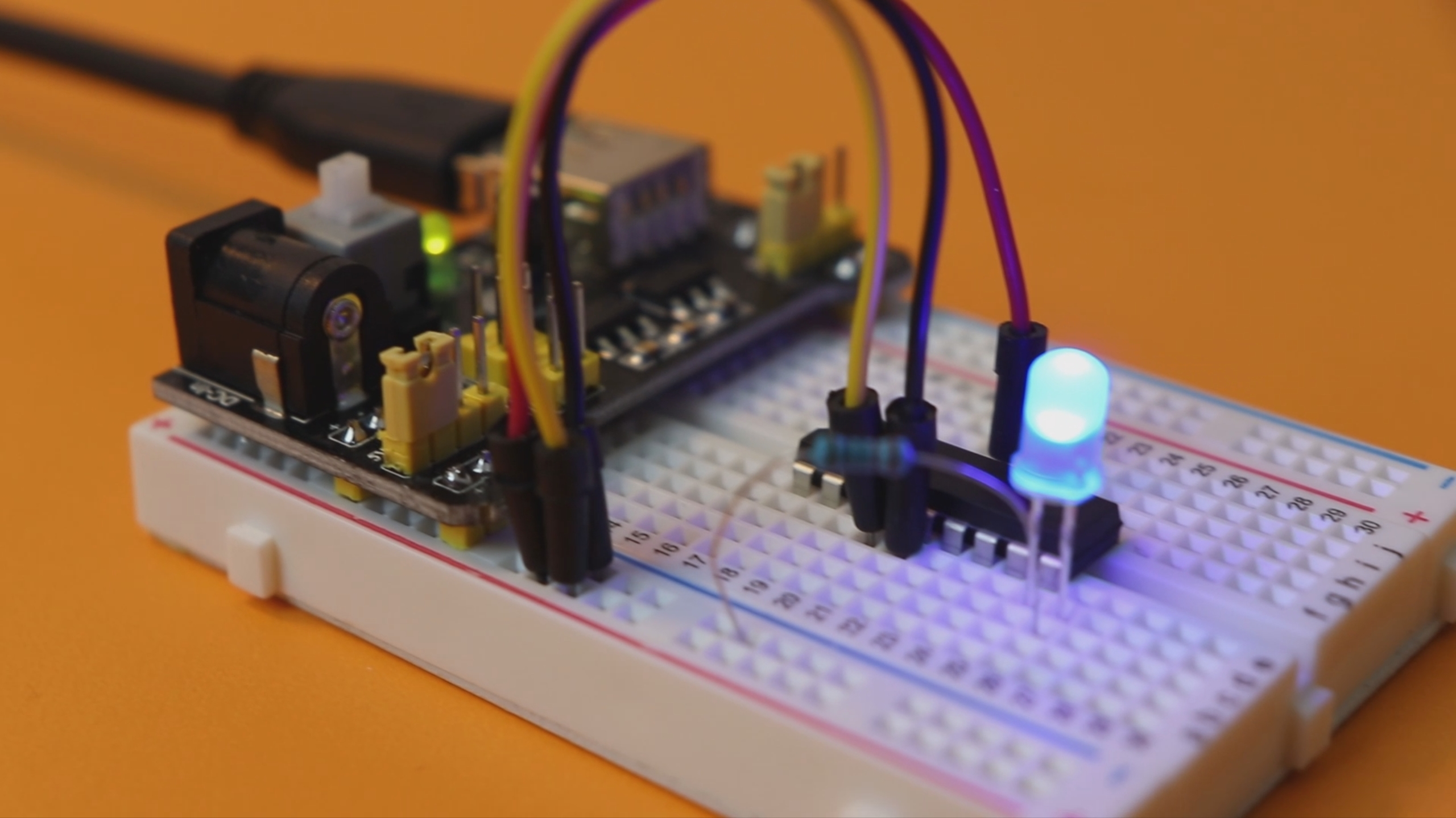
If all went well, and we press the power button, then we should see the LED light up and blink! Like this:
What if something goes wrong?
Electronics can be frustrating. I have spent countless hours troubleshooting circuits. A waste of time? On the contrary! I believe that finding mistakes in circuits-although frustrating-can be quite rewarding. You learn how to think logically, and you tend to not repeat the same mistake twice (after a while). Yeah, yeah, I know, it sounds boring, but I really think this is true.
Here are some possible mistakes to avoid:
- Did you plug the LED in correctly? Remember that LEDs have an anode (plus pole) and a cathode (minus pole), indicated in the schematic above with a "+" and "-" (and also explained in our LEDs 101 article).
- Are all jumper wires connected to the breadboard? Sometimes there can be loose contacts.
- Is the PIC16F627A plugged in upside down? Make sure the notch is facing upwards!
- Is the power supply plugged in completely? Are the jumpers set to the +5V configuration?
- Did you flash the PIC with the hex file? This is very important! If you don't flash the PIC, the circuit won't do anything :)
- If there is any other weird behavior, drop me an email. I am sure we can figure it out together!
Final thoughts?
Please let me know what you think! I hope this project sparks your interest (and I also hope that no actual sparks will fly) and shows you how much fun it is to build something with wires and electronic components.
In the upcoming weeks I hope to write a bit more about reading and drawing circuit diagrams, because for more complicated projects it is not really feasible to draw them by hand anymore. Also, we might start with some more interesting projects, now that we have the basics nailed down!
As always, thank you very much for reading, and I hope to see you again soon!
YouTube video
I covered this entire project in a dedicated YouTube video:
