Your first microcontroller program!
April 19, 2019 • tutorial
So last week we learned how to transfer a hex file onto a PIC microcontroller using the PICkit3 and the MPLAB X IPE software. For this week's post I think it will be nice to go through a very simple program that makes an LED blink.
In this post you find everything you need to know to create a program (also called “source code”) that makes an LED blink. At the end of this article you will have a hex file that you can transfer to your controller! Exciting!
Yes, yes, I know, it is the stereotypical beginner's program, but I think for a good reason. I hope it is not too boring for you, but I think it is always a good idea to start simple. Who has the time to go through an entire detailed in-depth tutorial on their first trip into the wonderful land of microcontrollers?
So, instead of giving an in-depth tutorial, I rather want to take a simple program and just explain what it does. Others have written many many excellent coding tutorials for PIC controllers, and it would be a bit silly in my opinion if I tried to compete with that.
Let's pick a controller
I decided to focus on the controller with the name PIC16F627A. The name is a mouthful, I know. So let us just call it the 627A from now on. The PIC just differentiates its name from other controllers, and the 16F just indicates that it belongs to the 8bit-midrange class of controllers. For us, it will be the 627A.
Alright, so let us take a careful look at the complete program, and then we can disect it line by line. Let's do it!
Step 1: Set up a project in MPLAB X IDE
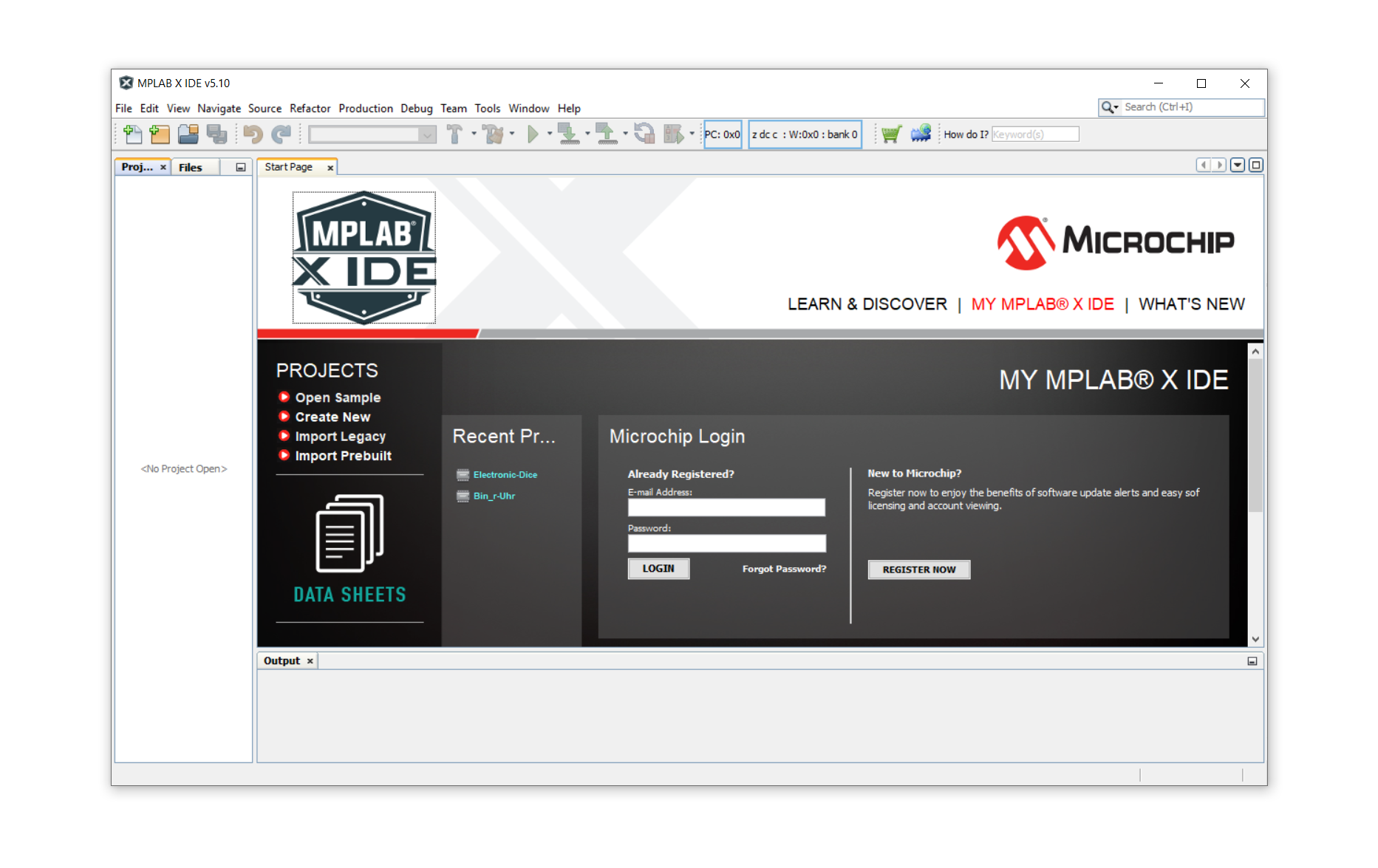
In the first step, we need to set up a project in the MPLAB X IDE which is a lot easier than it seems. Start MPLAB and wait for it to load.

MPLAB X IDE, once launched, will look like this:
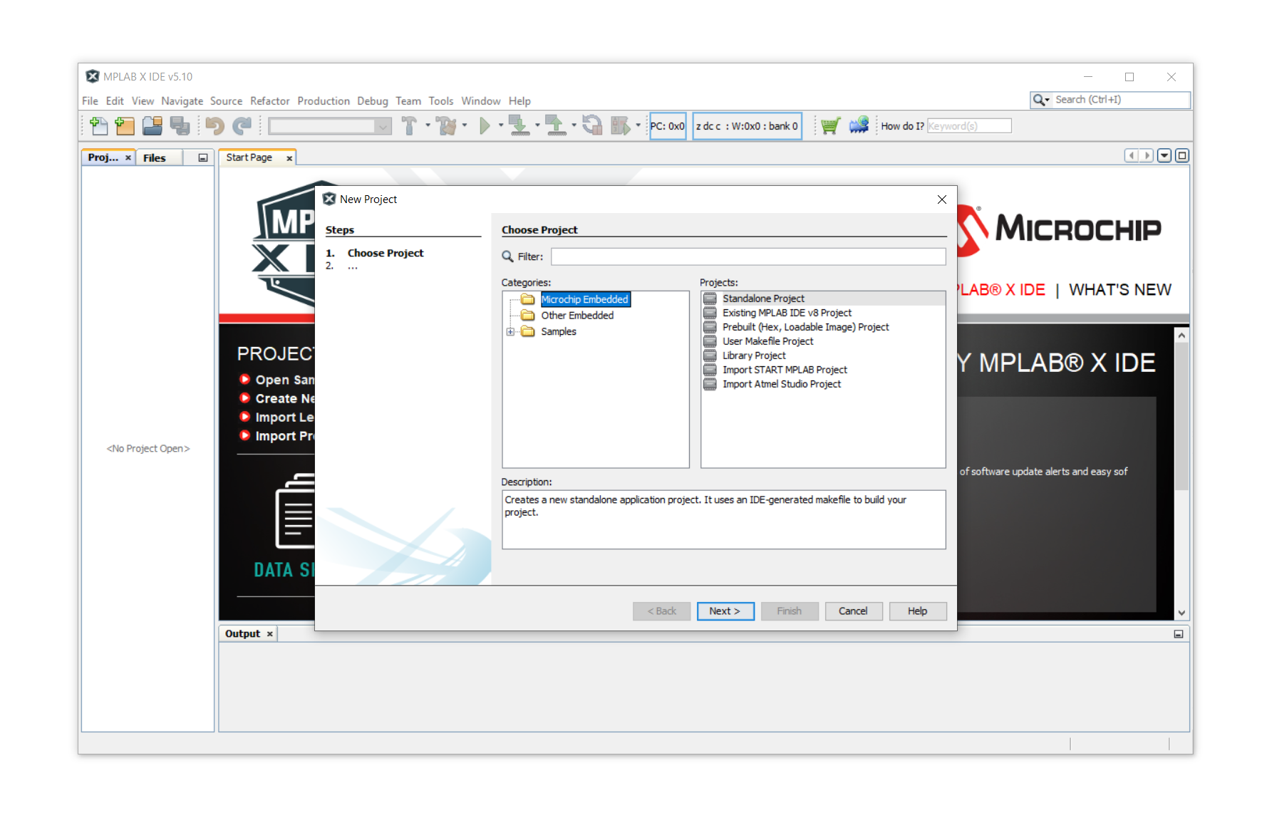
Click on File and then on New Project:
As a device we will select the PIC16F627A.
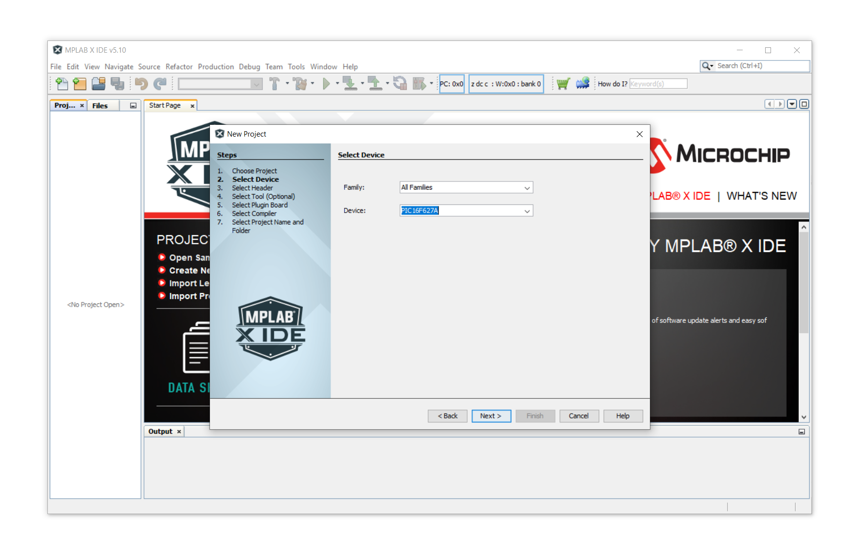
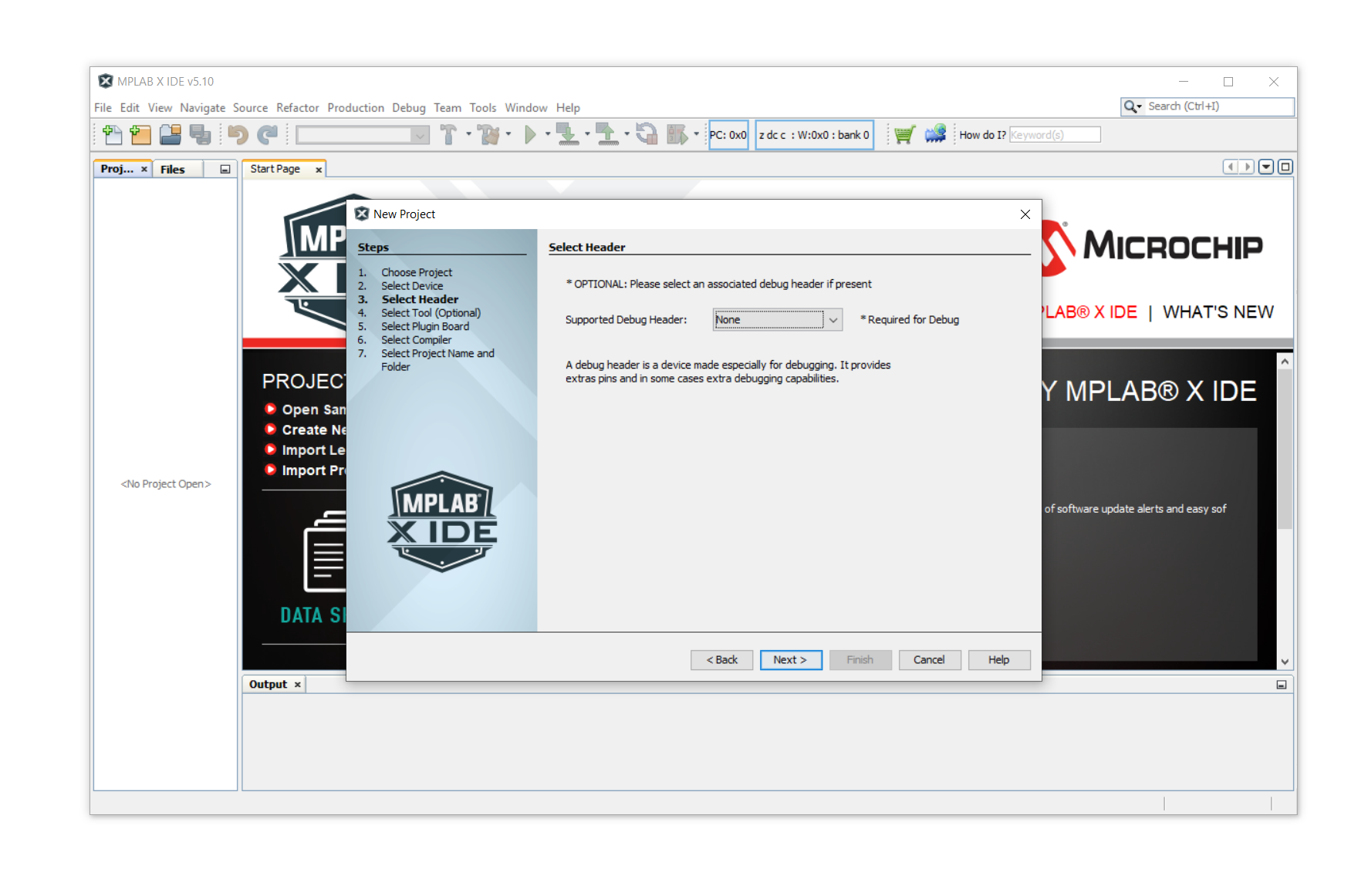
Then lick on Next, and also on Next in the window that follows:
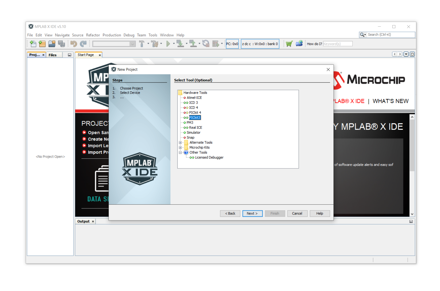
Then we select our programming tool, for which I am using the PICkit3, so this is what I select in this list. Click on PICkit3 if you also use it, and then click on Next.
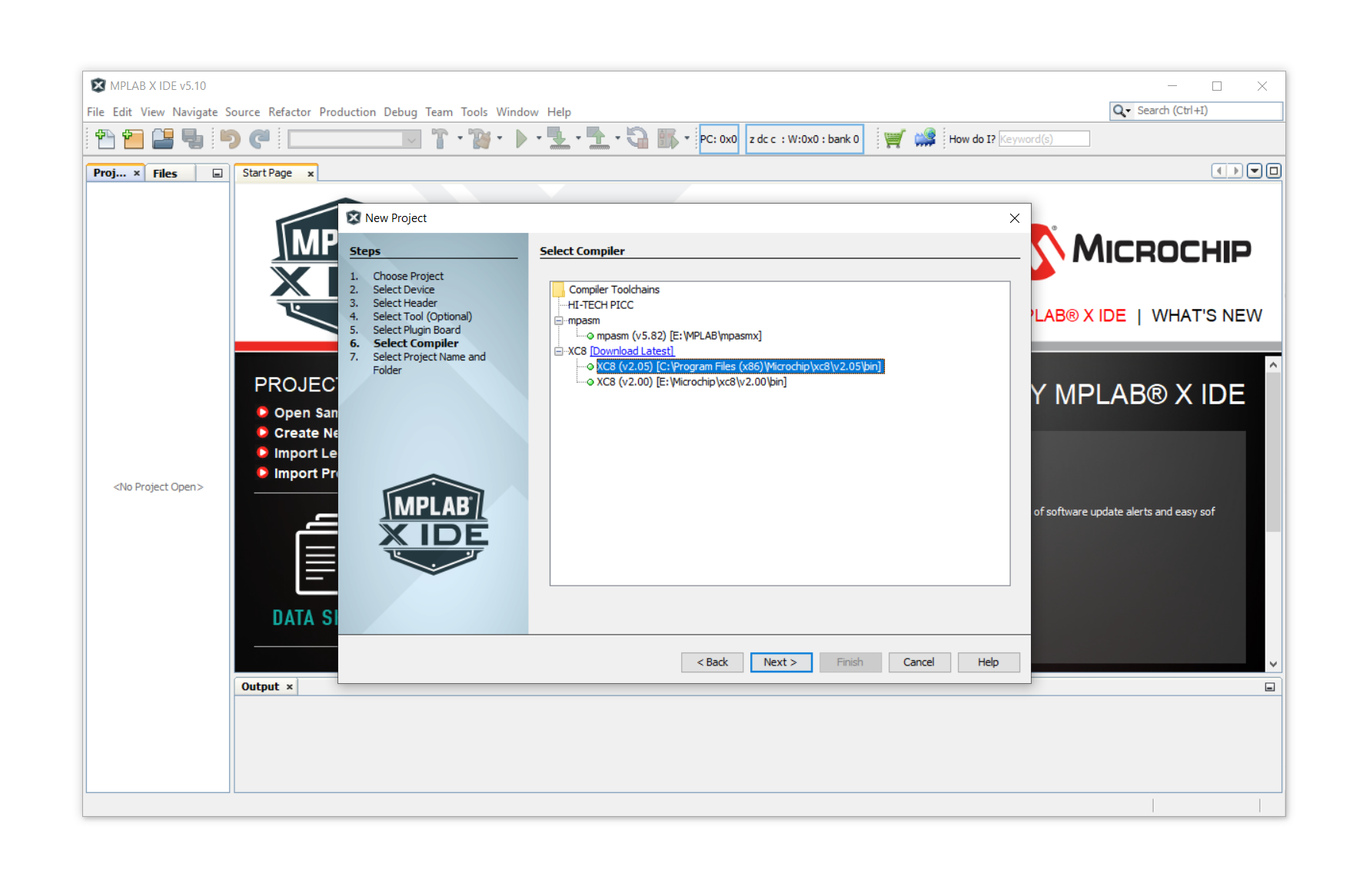
As a compiler just select any XC8 compiler (which will be automatically installed when you install MPLAB X IDE, so don't worry about it). If for some reason it is not installed you can download it for free here. Select XC8 and click on Next.
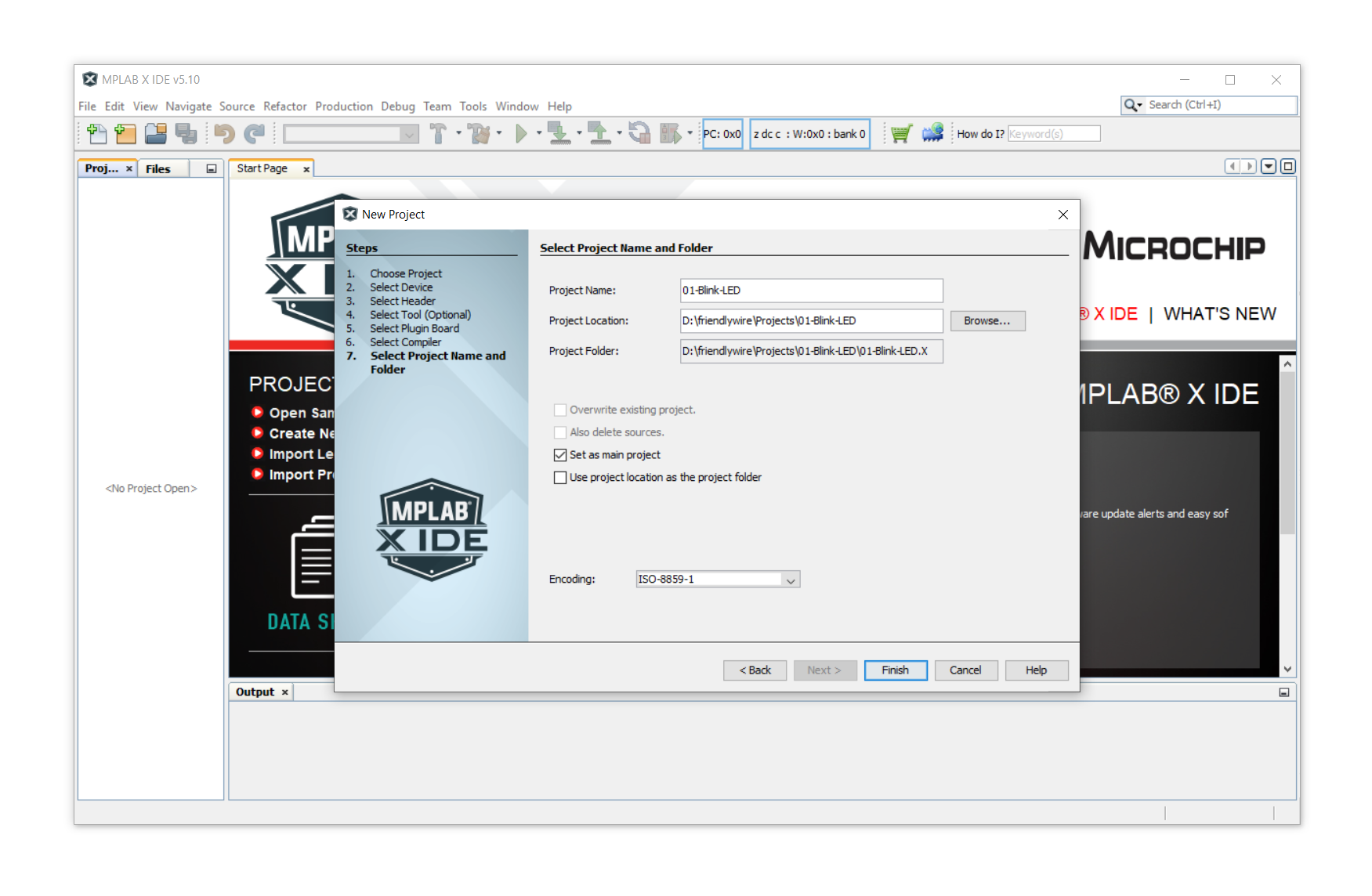
Then we are almost done, all we have to do is select the location of our project and give it a name. After you have made these life-changing decisions click on Finish.
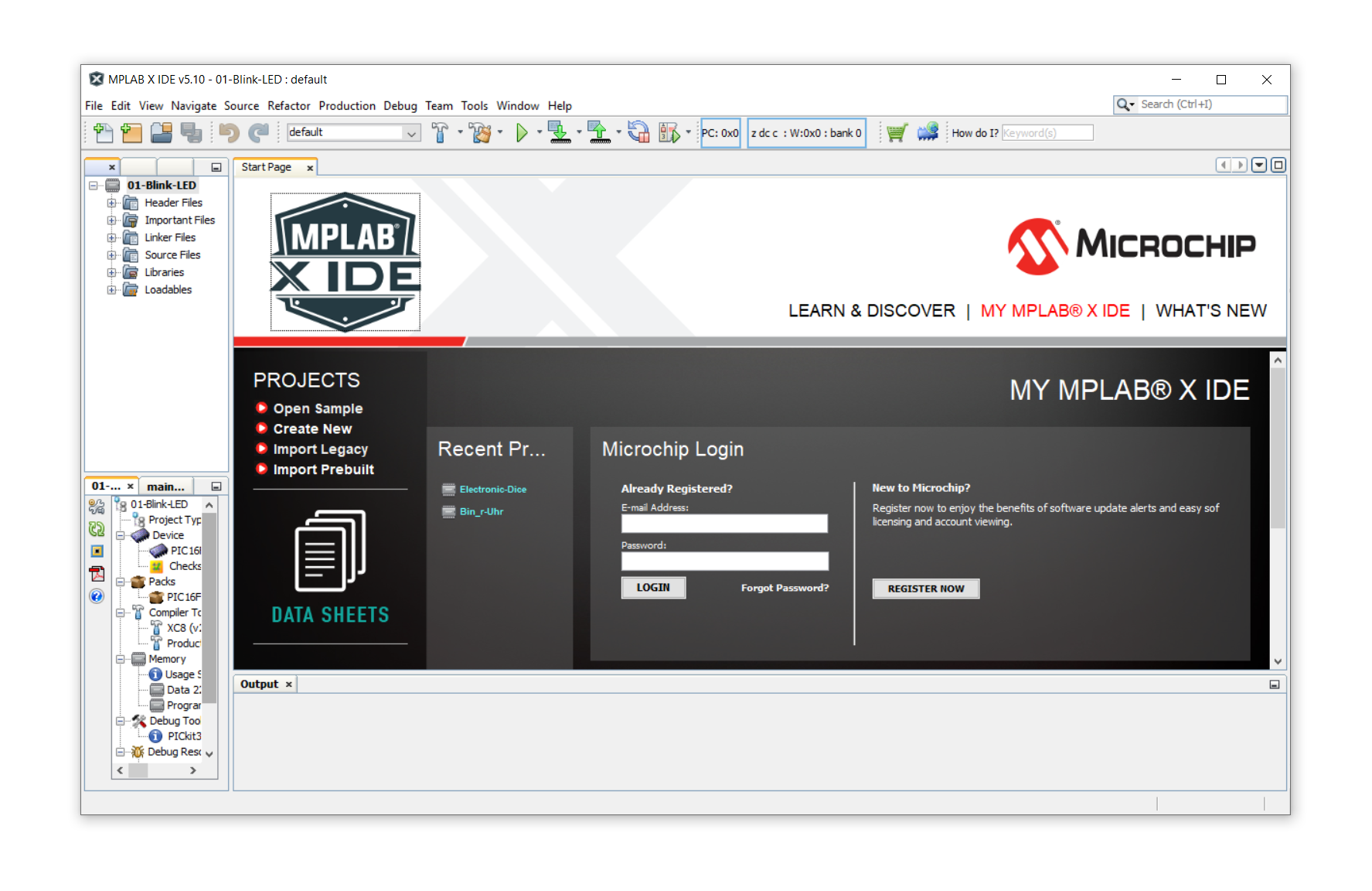
The project is all set up and ready to go!
Step 2: Create the main.c file
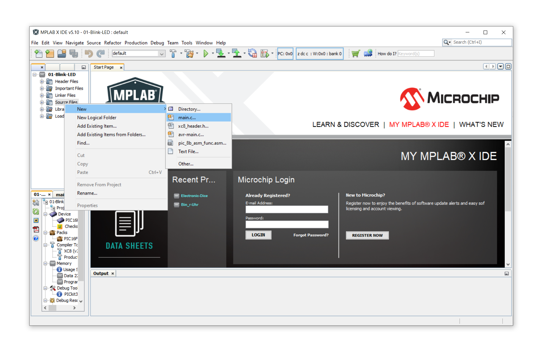
Now we need to tell the project that we want to start writing our program! For that we have to create a source file. Right-click on Source Files on the left-hand side, click on New, and then select main.c in the menu:
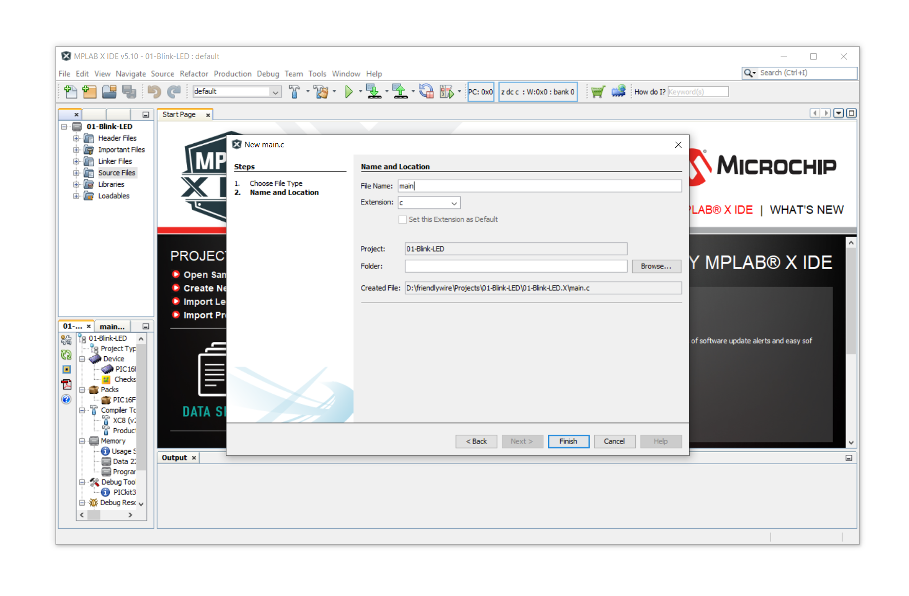
In the next window you can select the file name, for which I suggest main, but it can be anything you want. Then click on Finish.
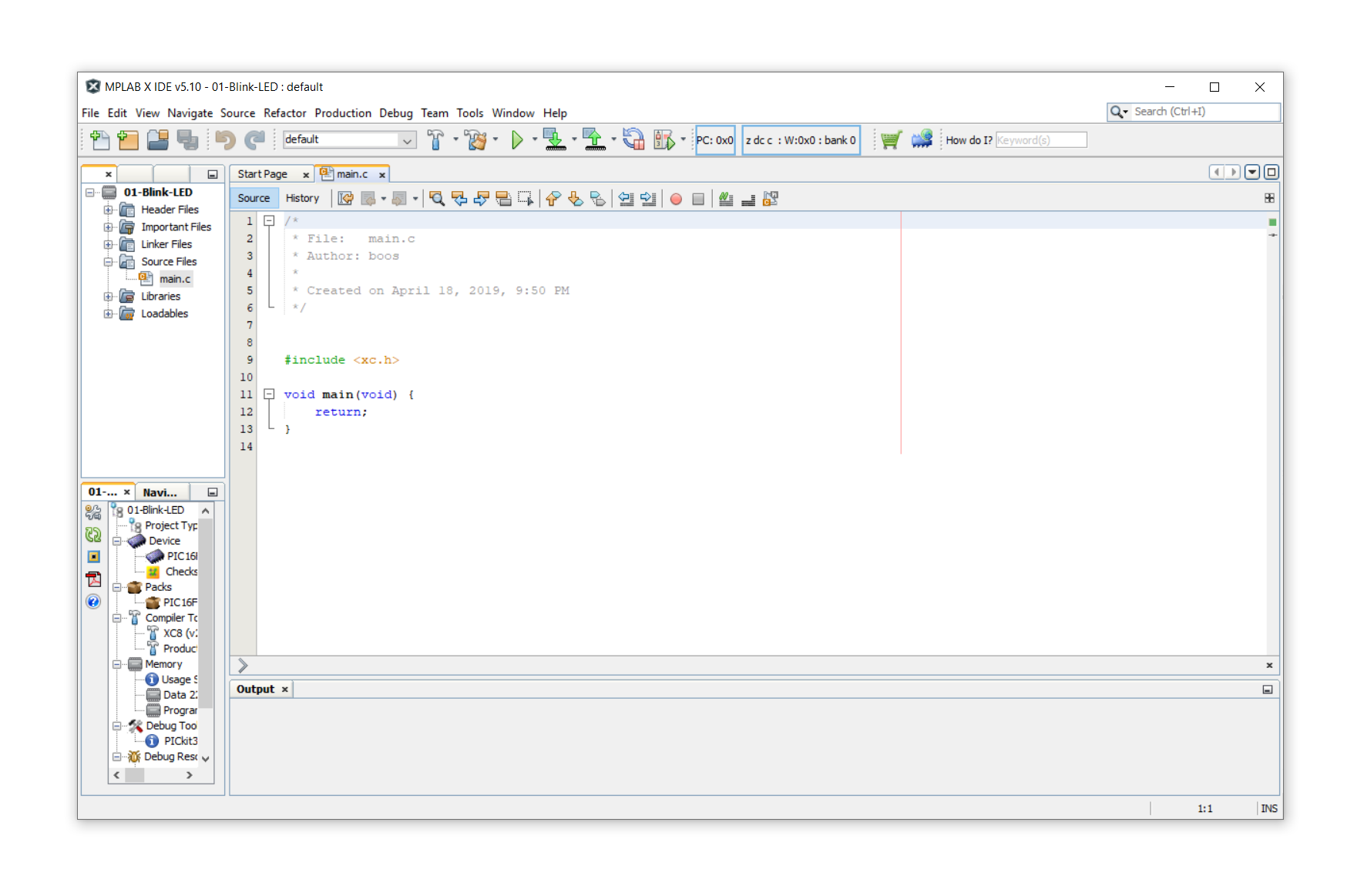
You will be presented with the automatically generated main.c file:
Step 3: Set the configuration bits!
Okay, now we need to set the so-called configuration bits. If you don't understand this part at the first reading that is completely OK, just follow the steps and you will be fine.
Configuration bits tell the controller in which operation mode we want to run it. Controllers come with many features, and some of them can be turned on or turned off using the configuration bits. These are bits (meaning that they can be set to either 0 or 1) which work as switches for each functionality.
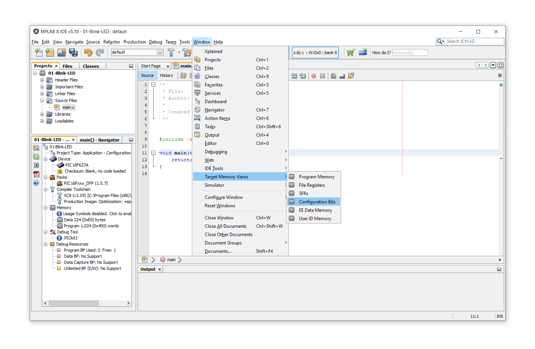
Luckily, MPLAB X IDE has a built-in manager for these bits to make it easy and convenient for us mortals. Simply click on Window, then on Target Memory Views and then on Configuration Bits:
In the lower bottom of the screen you will see the following Configuration Bits menu pop up. You can increase its size by pulling up that part of the window with your mouse. It looks like this:
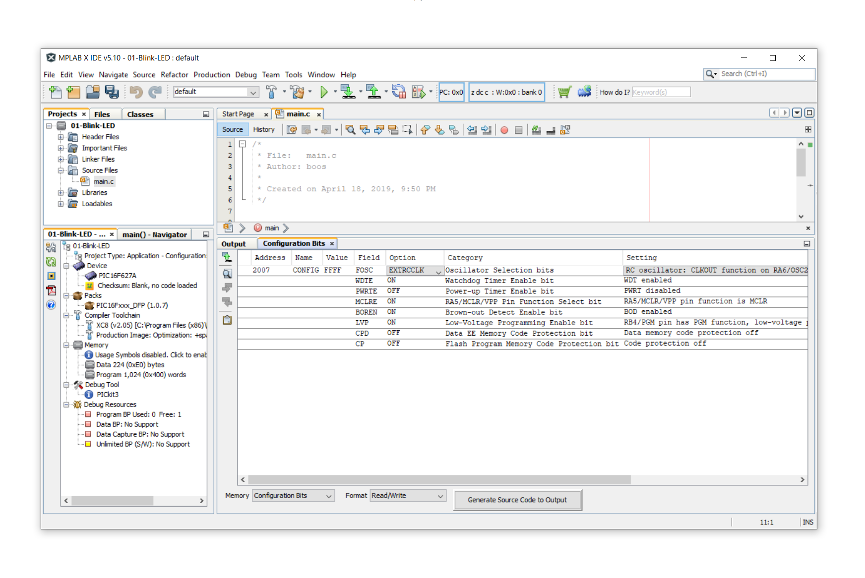
Under Field we see the option that we are changing, and under Option we see our choice for that, well, option. Never mind, sounds confusing. Click on the Option boxes and select the following choices:
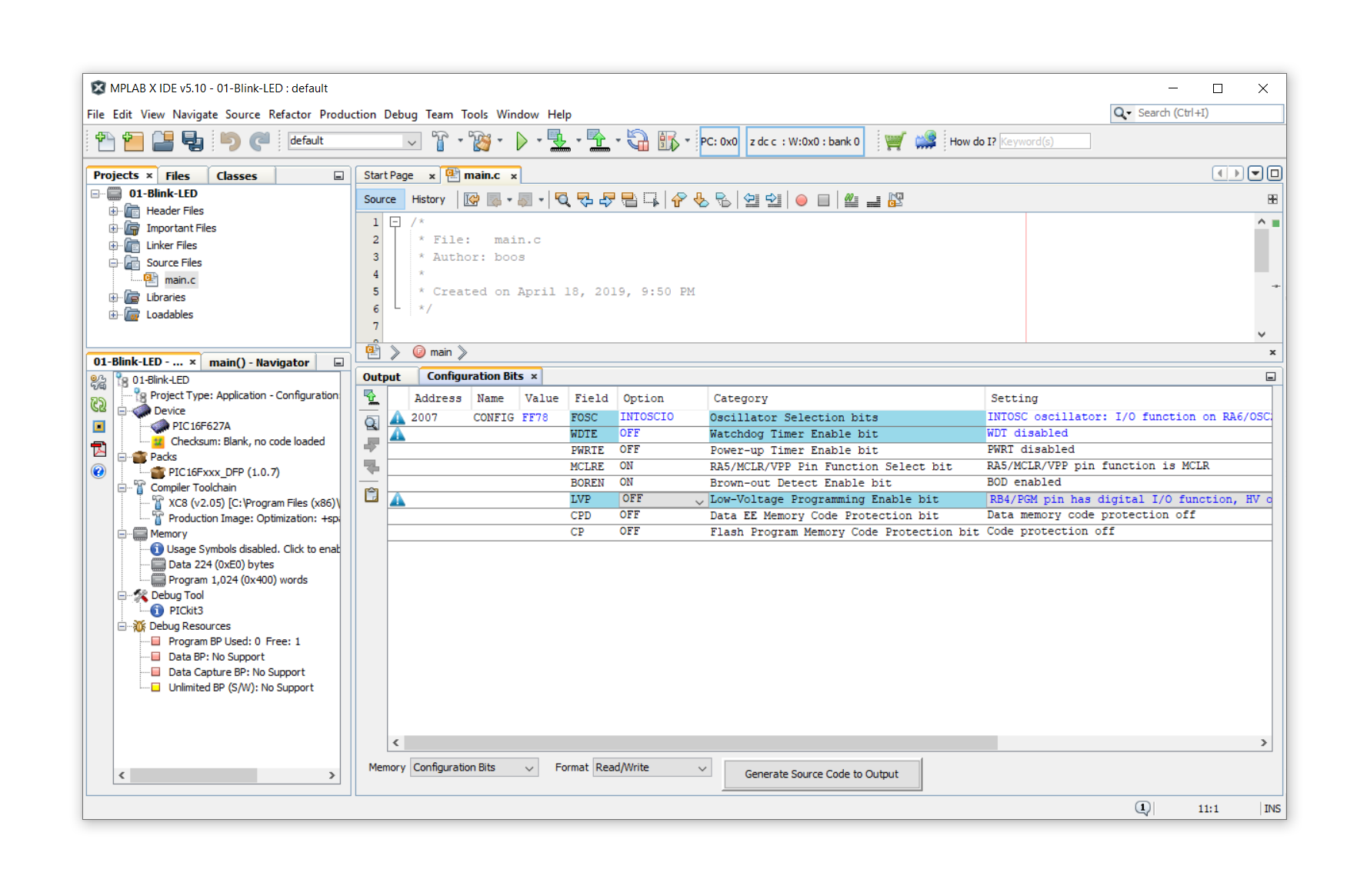
We can talk about what these options mean some other time, not now :)
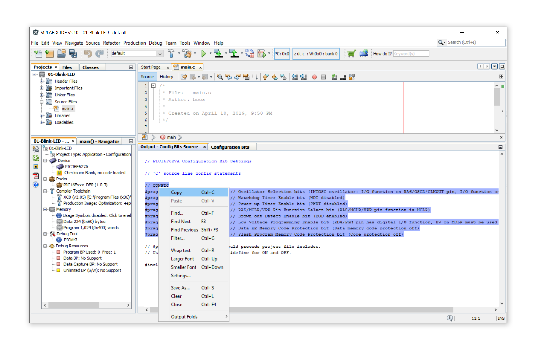
Now click on Generate Source Code to Output to proceed. You will get this prompt here which you can highlight with your mouse and then copy:
Then go back to your main.c file, which is still open in the background, and paste this code into the beginning of the file like so:
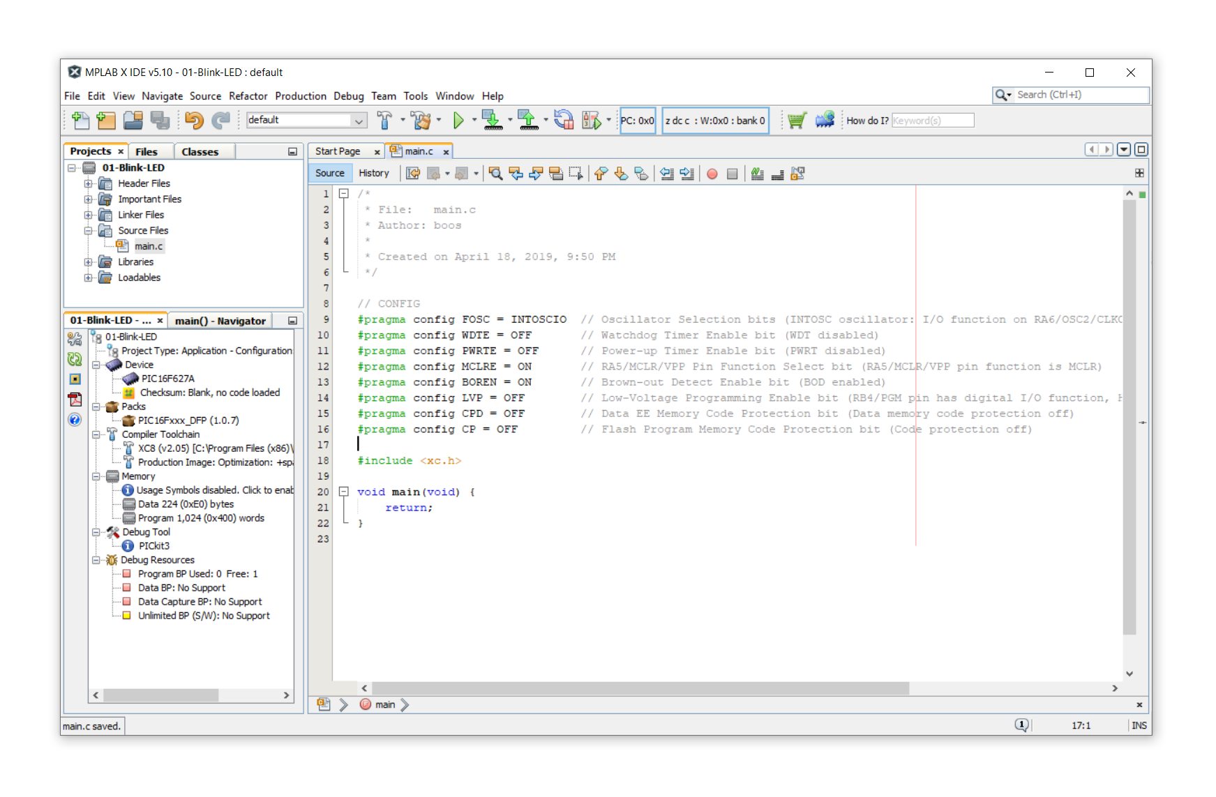
It is important that you paste this code before the #include line, just like in the image above. That's it, we have told the program what configuration bits we want successfully! Hooray!
Step 4: Writing the sample program
Without going into too much detail, this is the program we will insert after the #include line:
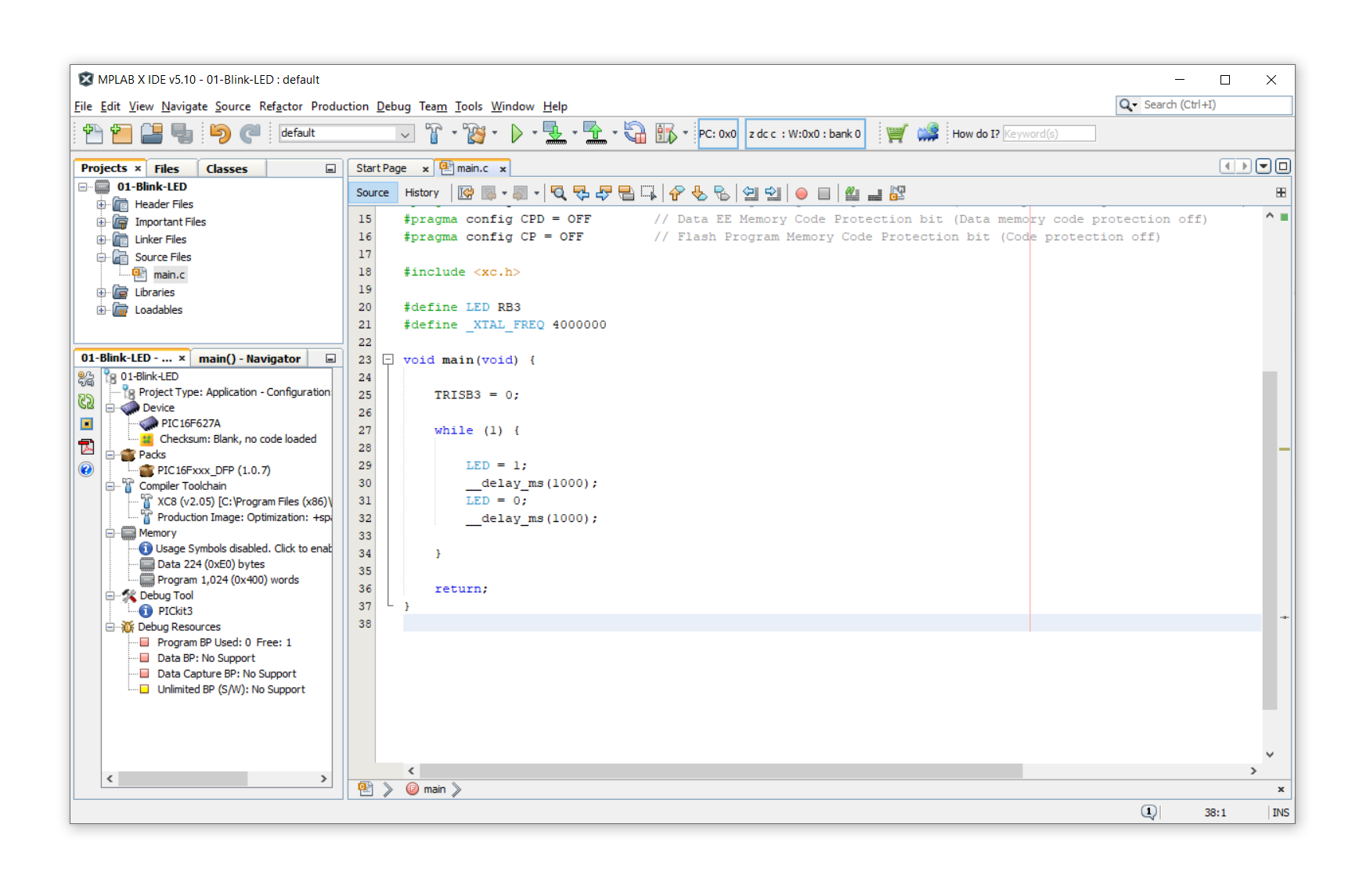
Here is the code ready to copy & paste:
#define LED RB3
#define _XTAL_FREQ 4000000

void main(void) {

	TRISB3 = 0;

	while (1) {

		LED = 1;
		__delay_ms(1000);
		LED = 0;
		__delay_ms(1000);

	}

	return;
}
Okay, let's talk a little bit about what that means, line by line:
- Line 1: We define the pin RB3 (which is one of the pins of the 627A) as the LED pin. This is done just for convenience.
- Line 2: We define the frequency of the internal oscillator to be 4MHz. It is not terribly important, we'll get back to that later.
- Line 4: This is the beginning of the main function. It is automatically generated by MPLAB X IDE, so we don't have to think a lot about what it means. All we need to know is that our program goes into the lines between line 4 and line 17.
- Line 6: We configure the pin RB3 to be of type OUTPUT since we want to connect an LED to it.
- Line 8: This is the main “loop” of the program. It will run forever and it will repeat everything between lines 9-14.
- Line 10: we switch on the LED.
- Line 11: we wait one second (or, rather, 1000 milliseconds). This is why we had to specify the oscillator frequency in line 2. If we hadn't specified it, the controller would not know how many instruction cycles it takes to wait one second.
- Line 12: we switch the LED off.
- Line 13: we wait another second.
And that's it! Not too bad, eh?
Step 5: Compile the program and generate the .hex file
In last week's post we learned how to “flash” a controller with a hex file. Now we are at the point where we can create our own hex file! Isn't this exciting?
To create our hex file we need to compile the source code we just wrote, and what that does is translate the human-readable code we just wrote into machine-readable hexadecimals. To do so, just press F11 (or click the hammer symbol in the toolbar). It will look like this:

See that green thing at the bottom? BUILD SUCCESSFUL. That's what I like to hear (and you too, I hope)! It means that our hex file has been successfully generated! Hooray!
But where is it? Go to your project folder, and go to the subdirectory dist/default/production . There are many files in there, but one of them has the ending .hex, and, you guessed it, that is our hex file!
Step 6: Transfer your hex file to the PIC
Now you are done! Last week we already talked about how to transfer your hex file to your PIC controller, and I invite you to look at that article :)
In next week's post I will talk about the electronics part. How do we assemble the LED test circuit, what tools do we need, and what should we think about.
Please let me know if you find this helpful, and please also tell me if something was not clear enough, and I will do my best to update it accordingly.
Thanks for reading this week's article, and I will see you again next week! Stay tuned!
Appendix: The complete source code
Here is the complete source code for your reference, feel free to copy & paste it into MPLAB IDE X and have fun with it! Let me know if something doesn't work.
/*
 * File:   main.c
 * Author: boos
 *
 * Created on April 18, 2019, 9:50 PM
 */

// CONFIG
#pragma config FOSC = INTOSCIO  // Oscillator Selection bits (INTOSC oscillator: I/O function on RA6/OSC2/CLKOUT pin, I/O function on RA7/OSC1/CLKIN)
#pragma config WDTE = OFF       // Watchdog Timer Enable bit (WDT disabled)
#pragma config PWRTE = OFF      // Power-up Timer Enable bit (PWRT disabled)
#pragma config MCLRE = ON       // RA5/MCLR/VPP Pin Function Select bit (RA5/MCLR/VPP pin function is MCLR)
#pragma config BOREN = ON       // Brown-out Detect Enable bit (BOD enabled)
#pragma config LVP = OFF        // Low-Voltage Programming Enable bit (RB4/PGM pin has digital I/O function, HV on MCLR must be used for programming)
#pragma config CPD = OFF        // Data EE Memory Code Protection bit (Data memory code protection off)
#pragma config CP = OFF         // Flash Program Memory Code Protection bit (Code protection off)

#include <xc.h>

#define LED RB3
#define _XTAL_FREQ 4000000

void main(void) {

	TRISB3 = 0;

	while (1) {

		LED = 1;
		__delay_ms(1000);
		LED = 0;
		__delay_ms(1000);

	}

	return;
}