How to get source code onto a PIC microcontroller
November 6, 2021 • tutorial
Say you have found a PIC microcontroller project that you really like. Because it uses a microcontroller it comes with source code that tells the microcontroller what to do. But how do you get that source code on the PIC microcontroller? This is what this tutorial is all about!
And first things first, this entire tutorial is available as a video with more details:
Okay, so how do you get the source code on the microcontroller? Here is an overview:
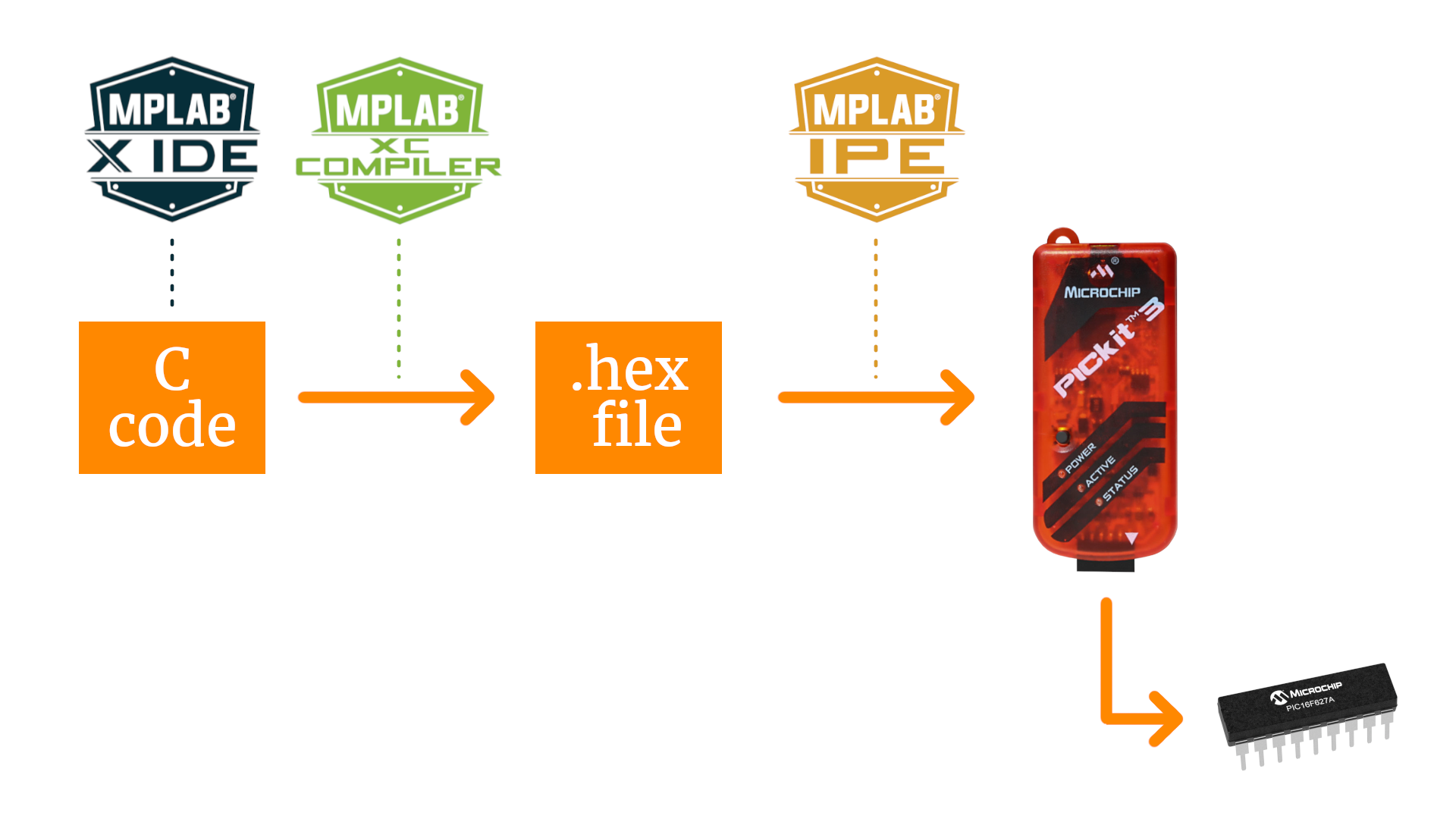
On the left is the source code written in C language, and on the bottom right is our PIC microcontroller on which we want to transfer the code.
- We use the MPLAB Integrated Development Environment (or IDE for short) to write our source code.
- Then we compile this code into a so-called .hex-file, and we will use the XC8 compiler to do that. All of that happens on your computer.
- Next we need a special device, called a programmer, that allows us to transfer this .hex-file from our computer out into the world onto the microcontroller, and we will use the PICkit3. It is connected to our computer with a USB cable, and on the other end we need to wire it up to the controller with five cables.
- And the actual data transfer is made with a third and final piece of software called MPLAB Integrated Programming Environment (or IPE for short).
Let's look at each one of these steps, one by one!
Step 1: Install the software
There are three pieces of software. The MPLAB IDE and IPE, which come in one download, and the XC8 compiler. You can download these programs here (for Windows, Linux, and Mac OS) for free:
Install them and follow the default options, that is all we need.
Step 2: Create a new MPLAB project
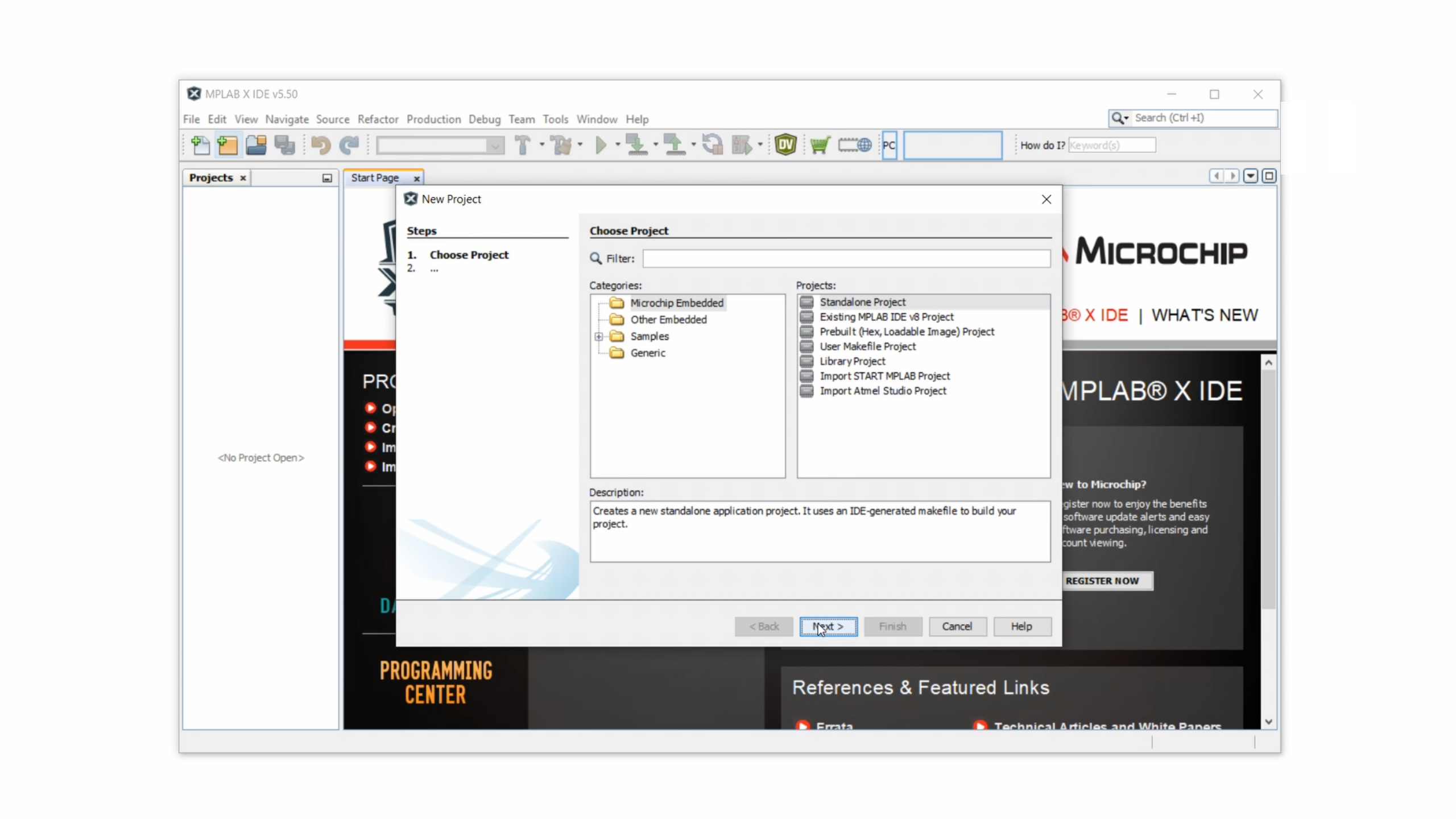
Now open the MPLAB IDE. Click on File and then on New Project. Select the option MicroChip Embedded on the left, and Standalone Project on the right, and then click on Next.
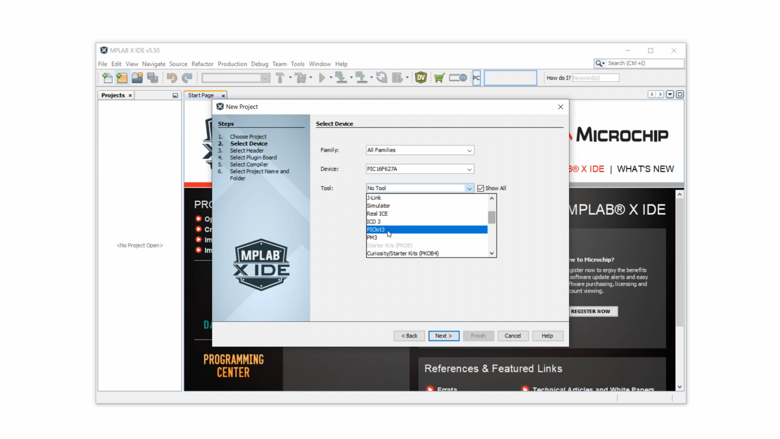
Now we have to select the PIC microcontroller that we are using, and here I will just use the PIC16F627A as an example. But if you are using a different one then of course enter that name here instead.
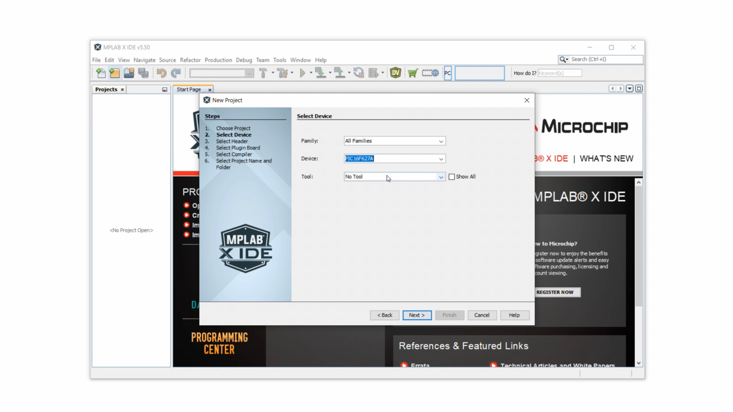
Then, under tool, first activate the option Show All and then select the PICkit3 in the dropdown list.
Click on Next, and because we won't talk about debugging today we can skip this window here and keep None selected before clicking on Next again.

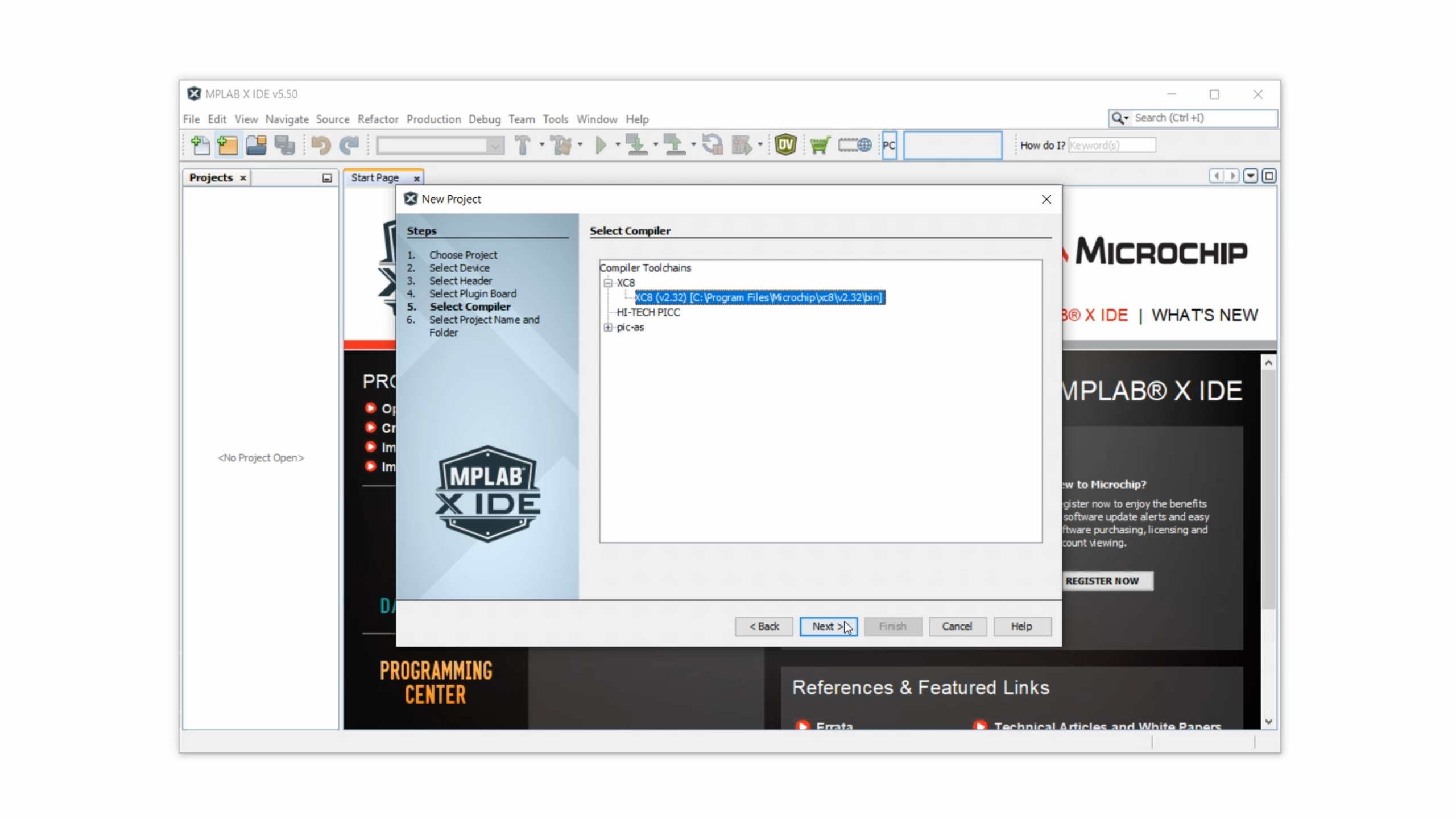
Now it's time to select our compiler. Select the XC8 compiler from this list here, which is the compiler that we installed a minute ago.
Now we can select a name for our project, and I will just call it “Test,” and then we need to specify the location of the project folder. Click on Finish, and our project is all set up and it should now appear in the left part in the MPLAB IDE.

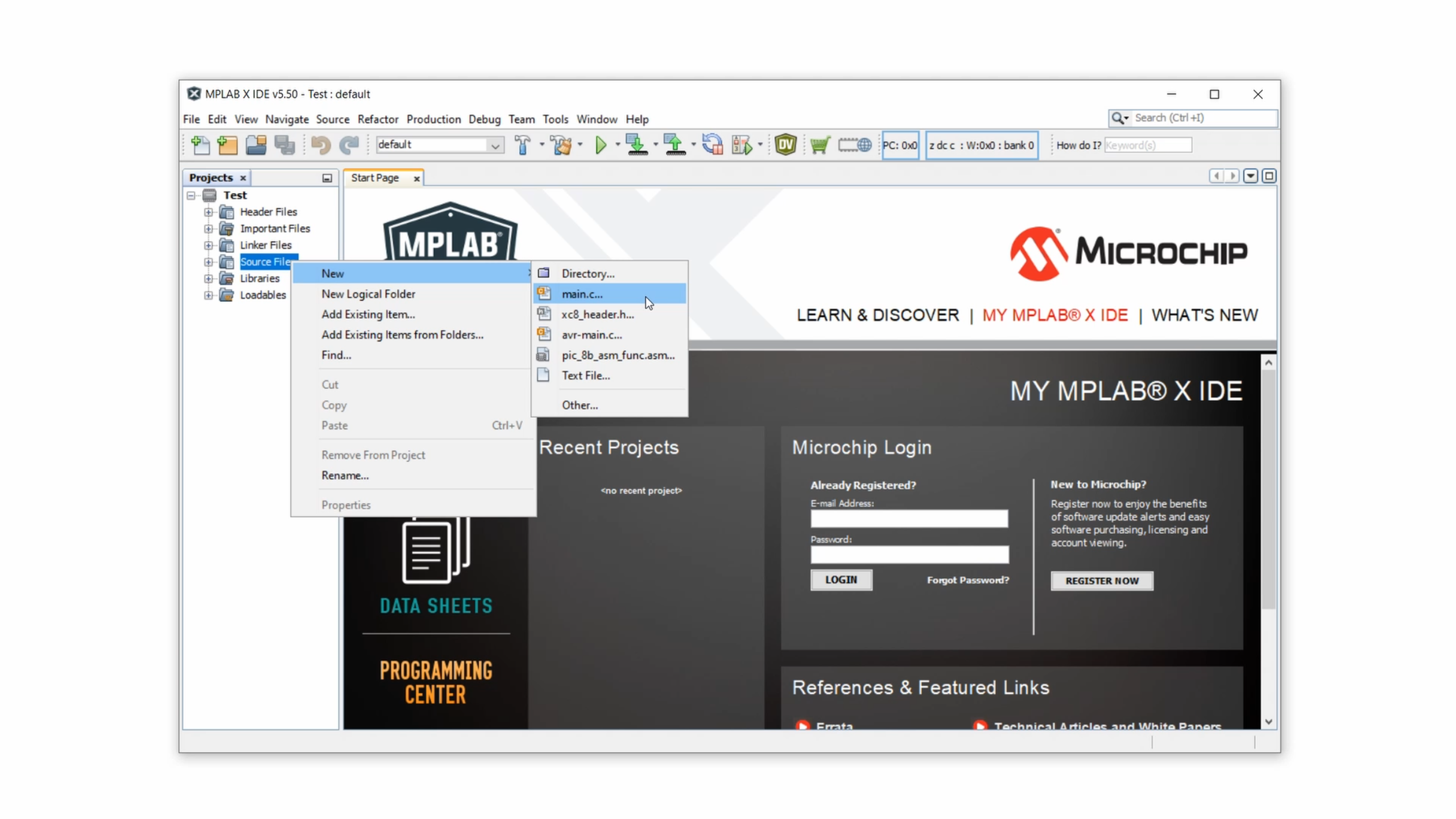
But for now it's still an empty project, so we need to create the main source file where we will write our C code. To do that, right click on Source Files, select New and then choose main.c.
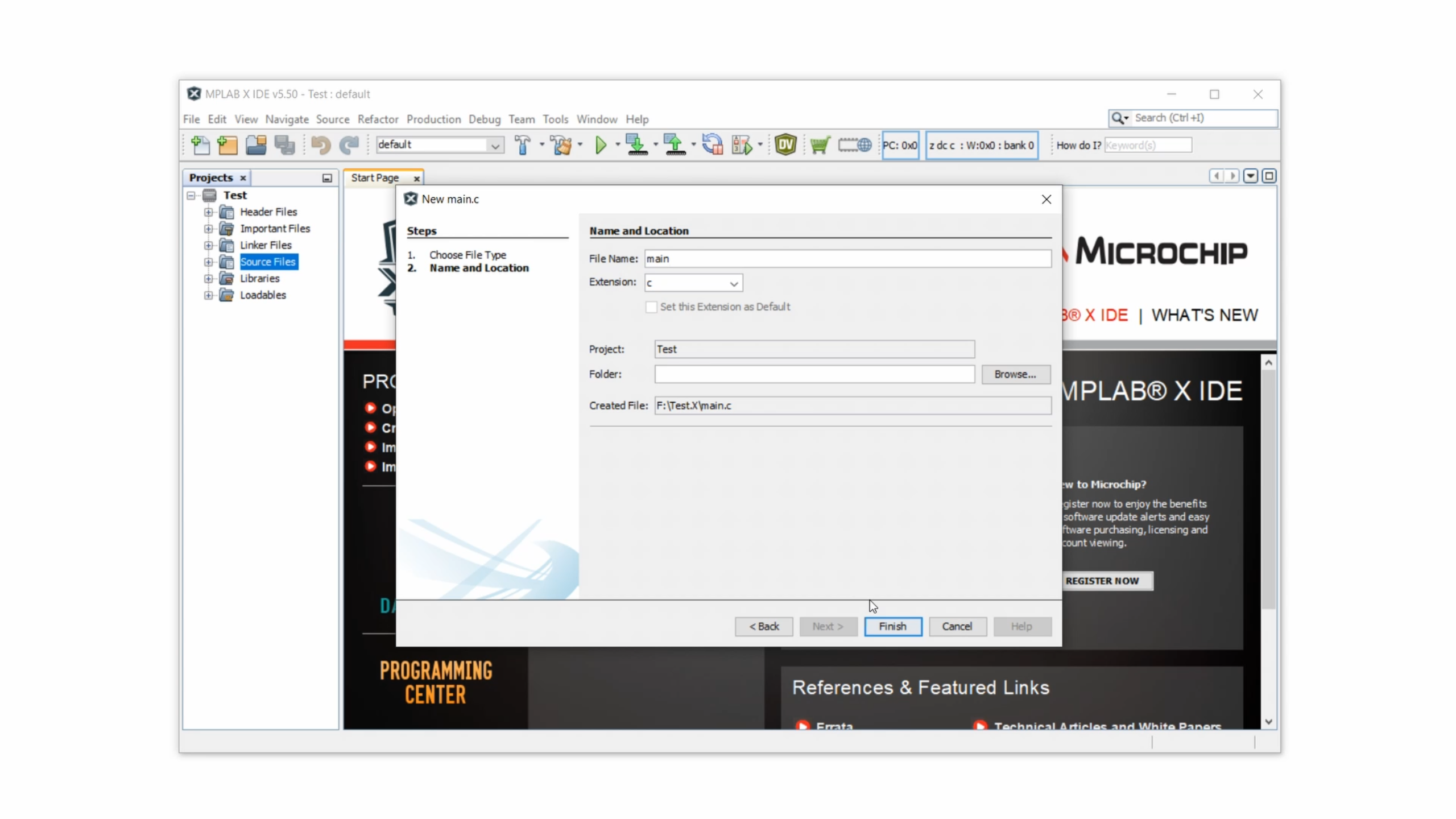
As a file name enter “main” and then click on Finish.
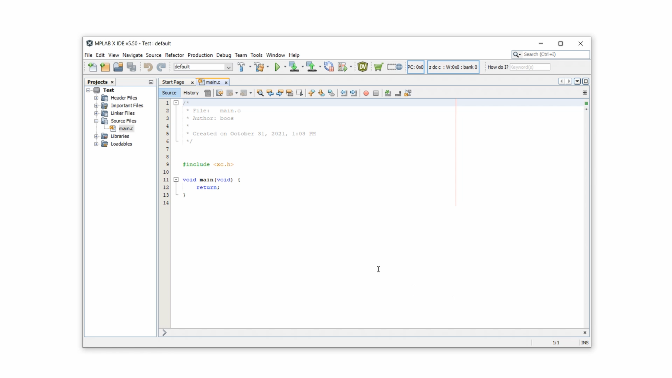
And what you see here is the barebone structure of a C program for the PIC16F627A controller:
Now you can either write your own code, or copy & paste the code from a website. For all of the tutorials and projects on this channel here you can always find the full source code at the bottom of the companion article. So as an example let us use the LED blink source code, our first program ever.

Make sure that this code is really written for the controller for which we set up the project. In this case, it has to be written for the PIC16F627A, which it is.
Step 3: Compile the C code
This code is written in C, and the language C has been designed in a way that it is nice to read for us humans. But a controller does not understand C directly, so we need to compile the C code into a set of simple commands that the controller actually understands. We use a compiler to do that, and that's why we installed the XC8 compiler. The resulting file is called a .hex-file, and it has that name because its format is in hexadecimal.
And to create this .hex-file, all we need to do is click the hammer & broom symbol:
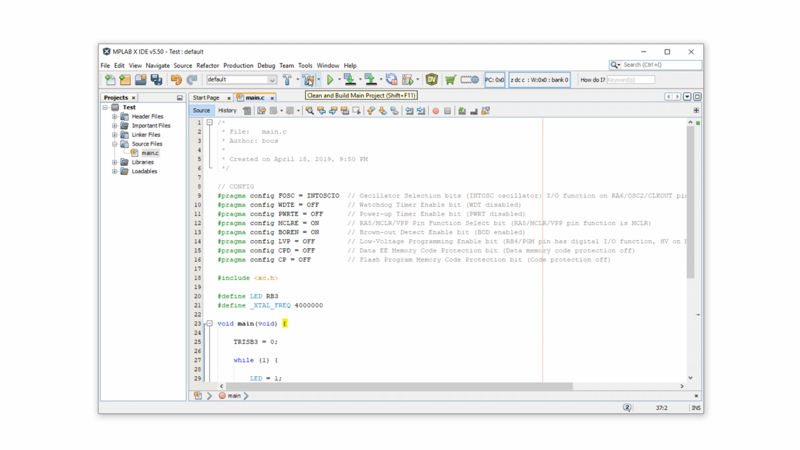
This cleans up all temporary project files and then compiles the source code into the .hex-file. Depending on the length of the source code this step can take a few seconds, but at the end it should say build successful at the bottom prompt here:
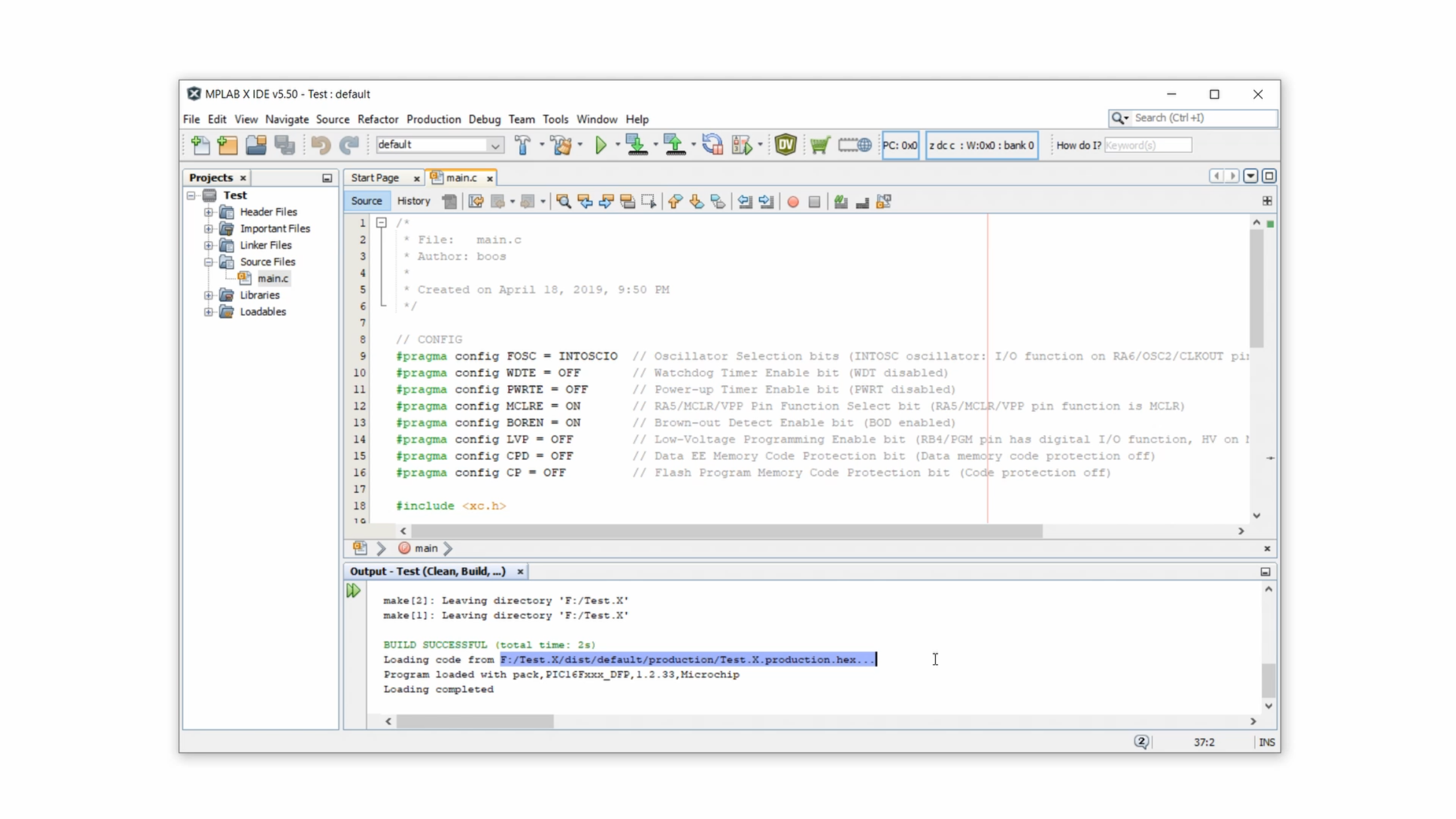
And the text right after that tells you where to find the .hex-file; go to the project folder, into the dist folder, then into the default folder, and then into the production folder, where the .hex-file is located under the name Test.X.production.hex.
Step 4: Connect the PICkit3
Okay, now we need to leave our computer and get into the real world. It's time to transfer the .hex-file onto our PIC microcontroller, and we will use the PICkit3 to do that. Even though it is officially out of date and no longer sold by MicroChip directly, you can still find unofficial versions online. In my experience they work great cost around $25. You can find links to where to buy the PICkit3 here.
The PICkit3 has a USB end that plugs into our computer, and on its other side it has a six-terminal connector to wire it up to our microcontroller. The little white triangle here marks pin number 1. Here is the pinout:
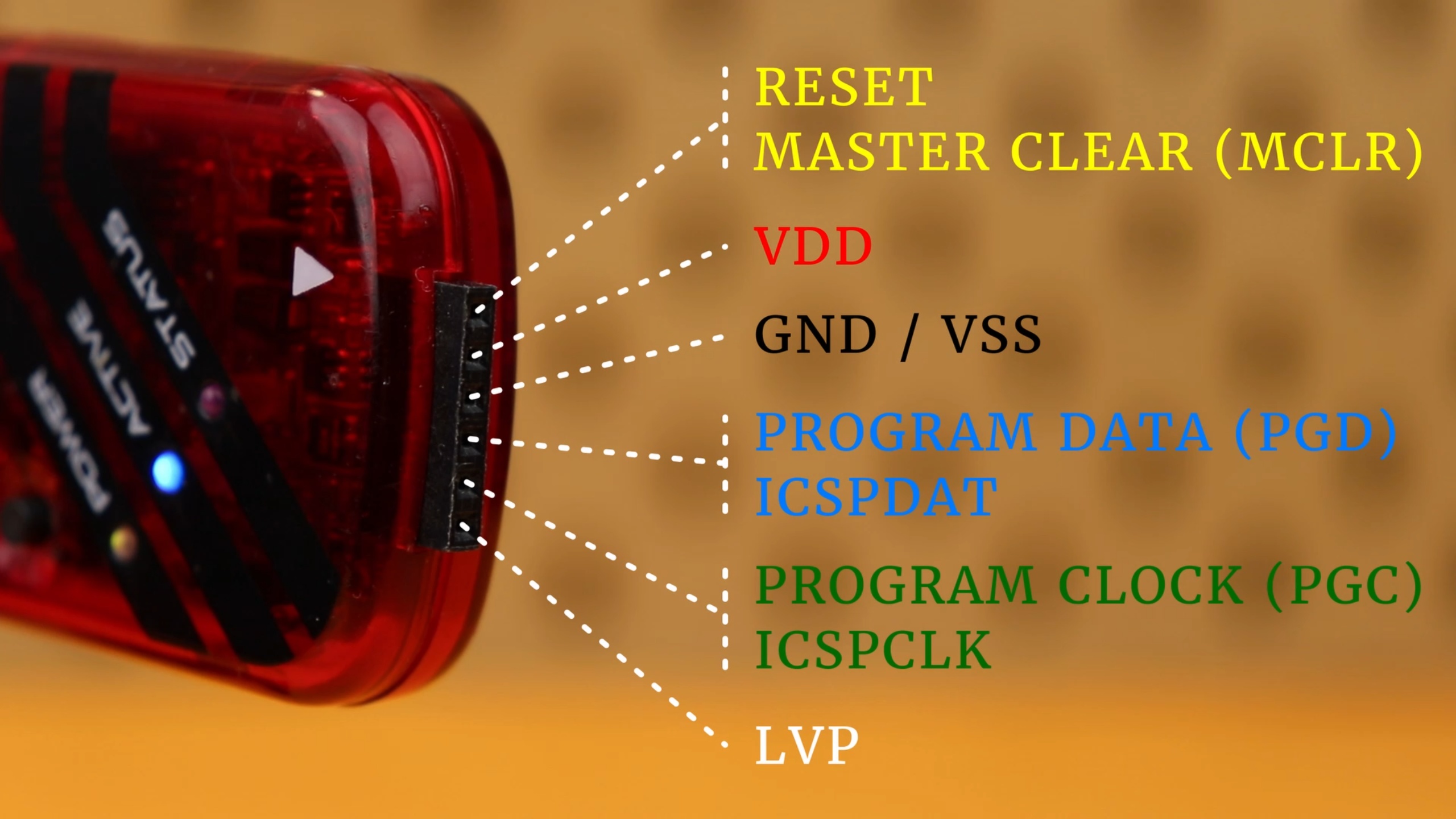
- Pin 1 is the the reset pin. It is also called “Master Clear” or MCLR for short;
- Pin 2 is where we connect the positive supply voltage of 5V, it is also called VDD;
- Pin 3 is the ground connection and also called VSS;
- Pin 4 is the data pin. It also goes under the name “Programming Data,” PGD, or ICSPDAT;
- Pin 5 is the clock pin. It's also called “Programming Clock” or PGC for short or ICSPCLK.
- And pin 6 is the low voltage programming pin, or LVP for short, but we don't use it today so let's just ignore it.
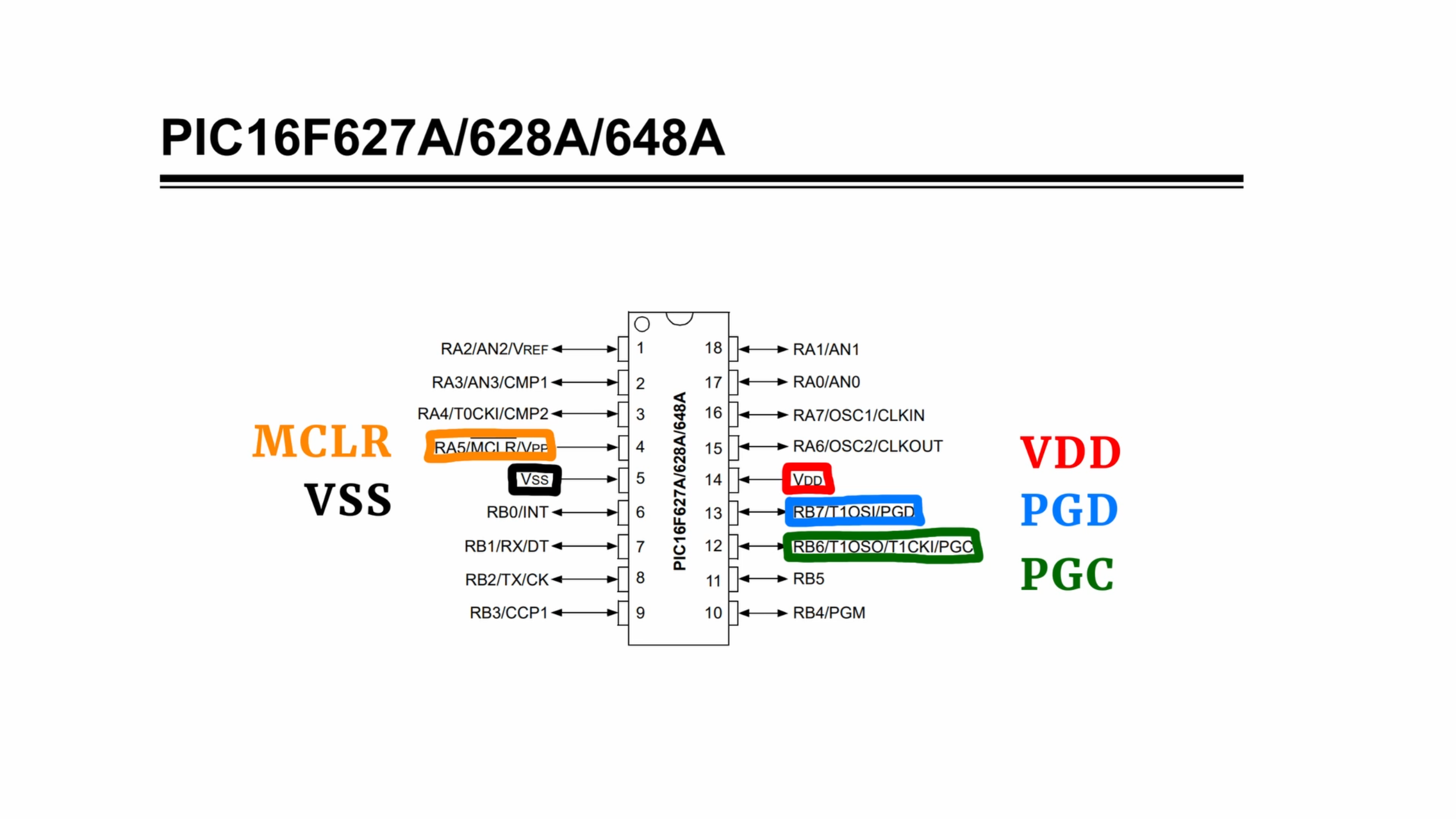
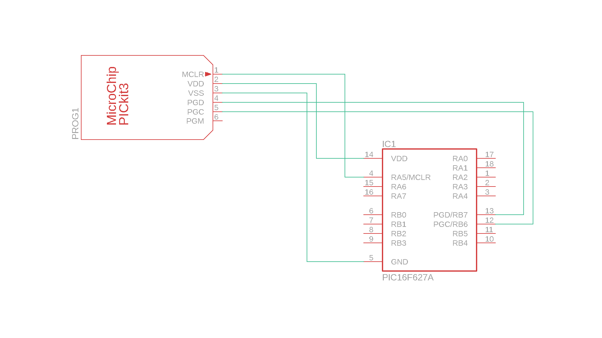
Now except for the last pin, all five pins have to be connected to our PIC microcontroller. Take a look at the datasheet of your controller and look for the pinout. Here is the PIC16F627A as an example:
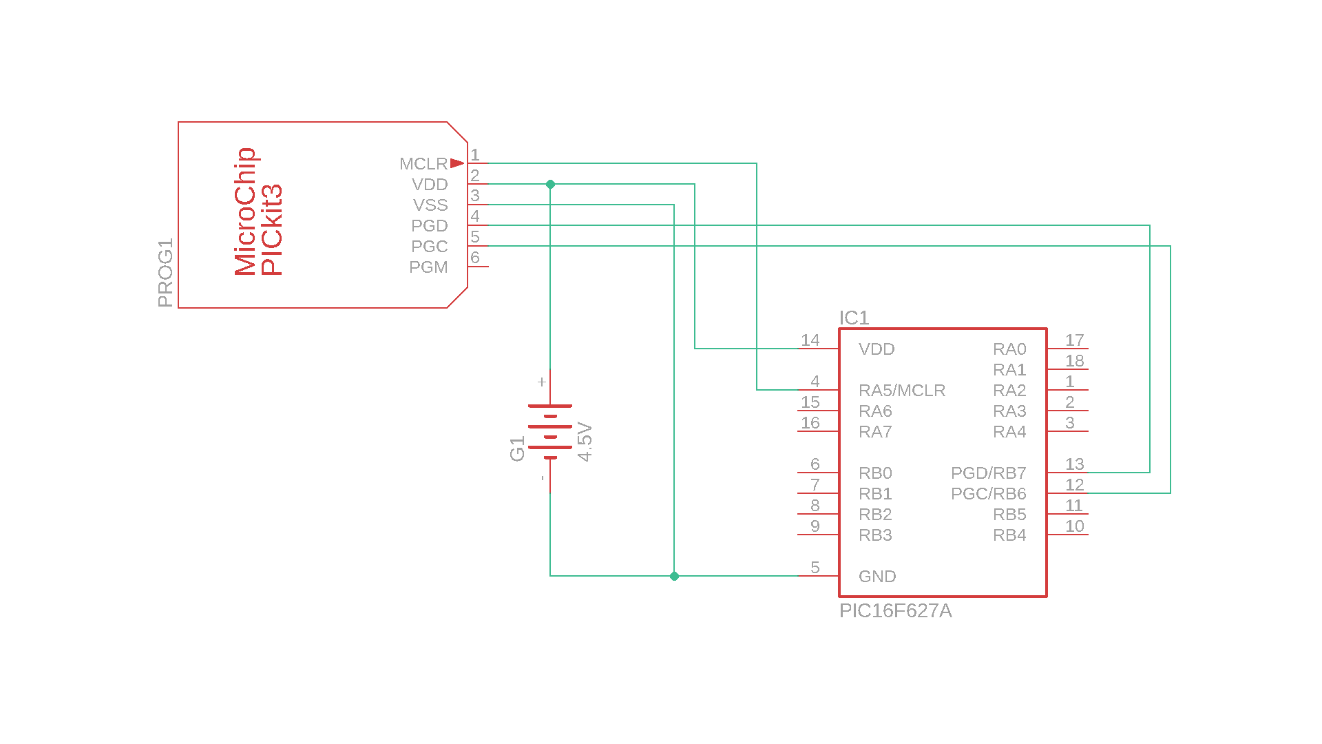
And this is how this looks like as a schematic, for our PIC16F627A example:
To build this you need a breadboard where you plug in your controller, and then you can use Dupont-style connectors to connect all five wires from the PICkit3 to your controller:
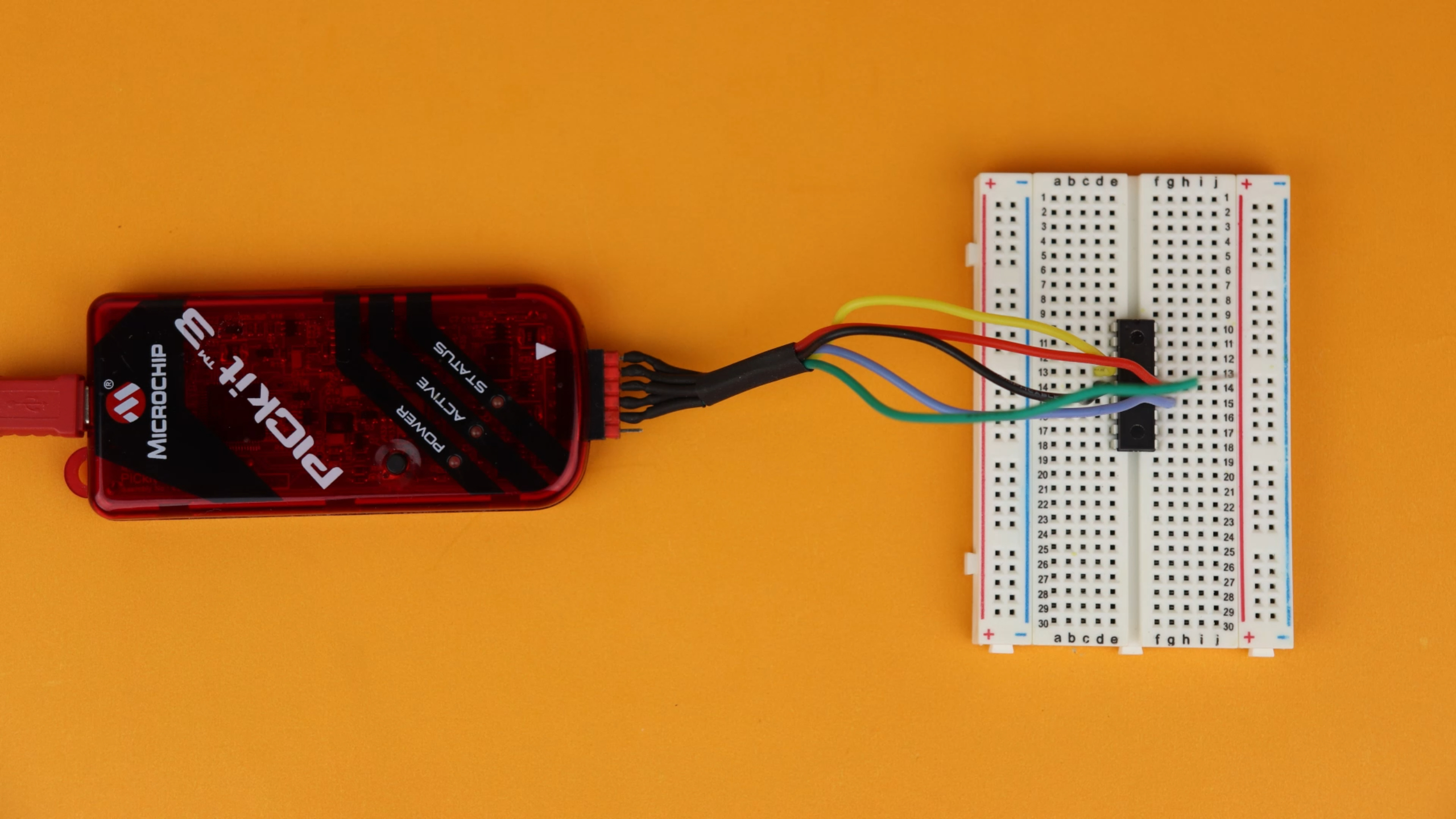
And then, when it's all connected, plug the PICkit3 into your computer on the USB end.
Step 5: Program the controller
Now open the MPLAB IPE. First things first, I like to switch into the “advanced mode” which you can do by clicking on Settings and then on Advanced Mode. Enter the default password, which is “microchip,” select the option keep me logged in and then click on Log in.

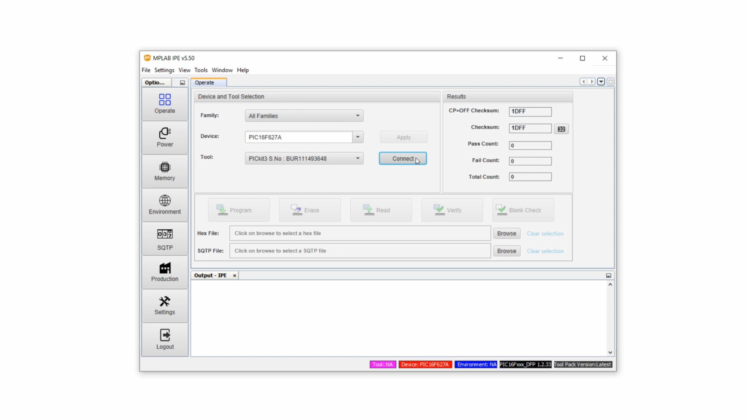
After adjusting ther aspect ratio a bit, the window should now look like this:

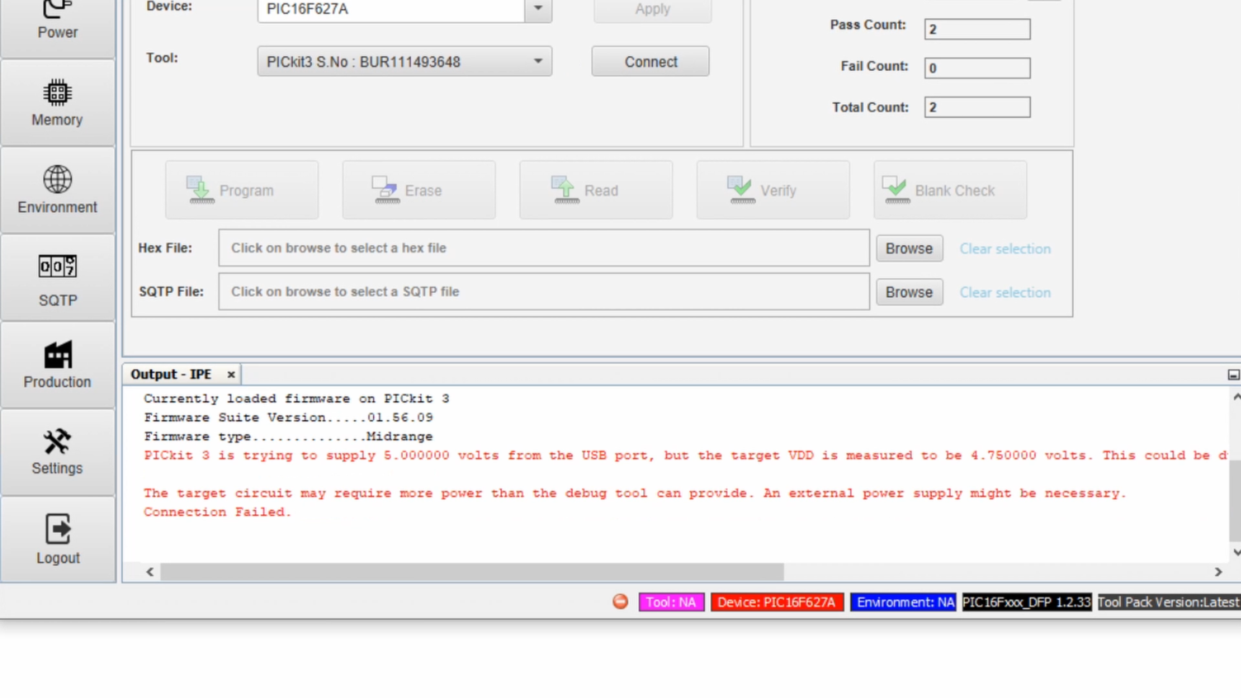
Next, under Device, type in the name of your microcontroller, which is the PIC16F627A in our case, and click on Apply. Under Tool the PICkit3 should already show up because we plugged it in earlier. Then click on Connect so that the MPLAB IPE can establish a connection with the programmer. (The blue symbol starts spinning, and sometimes this takes a while, and if a dialog window shows up you can just select “Do not show this message again” and then click OK.)
But it looks something went wrong here:

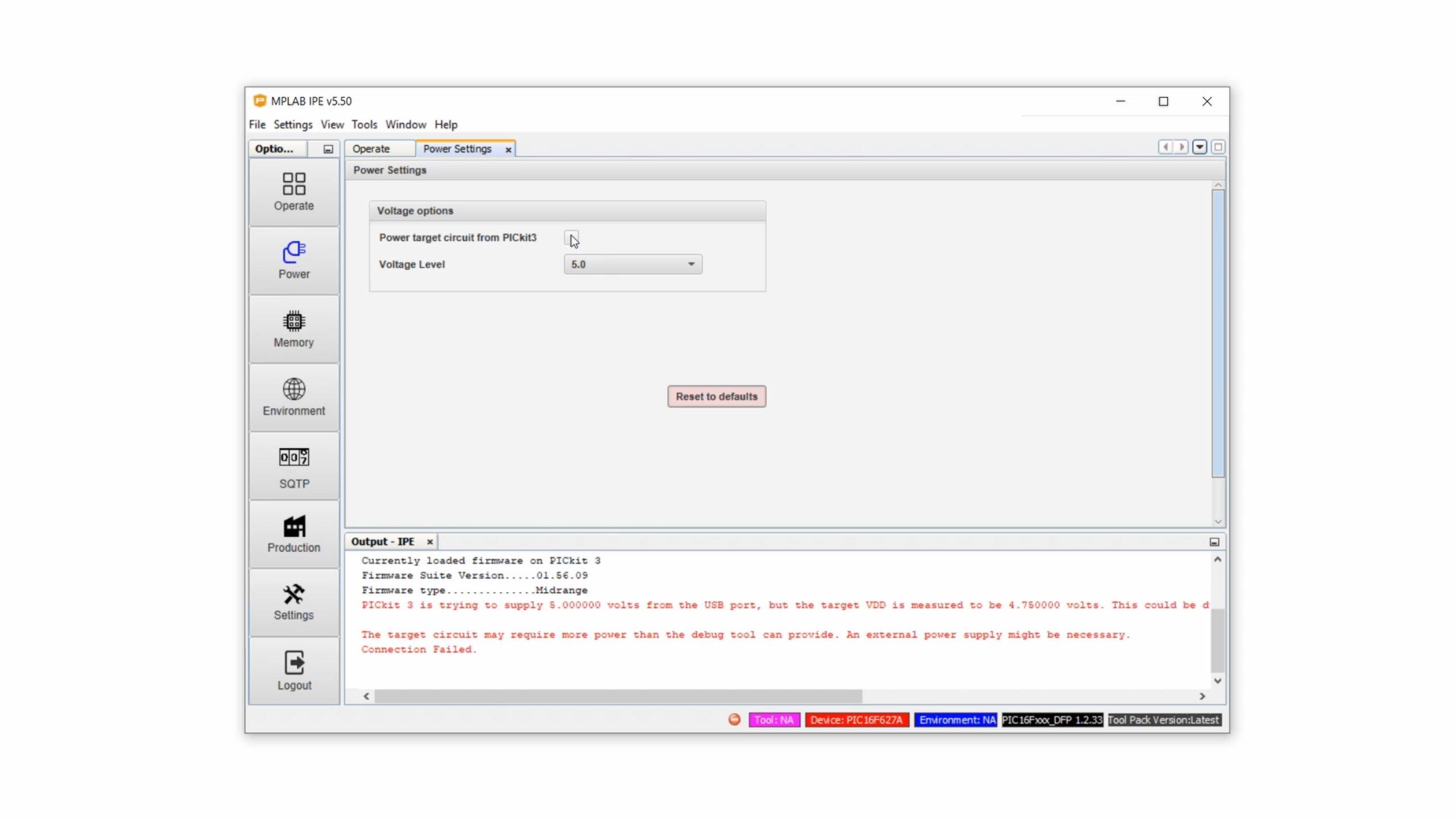
That's because we have to tell the PICkit3 to send out power as well. To do that, click on the Power tab on the left side and under voltage option select the option power target circuit from PICkit3:
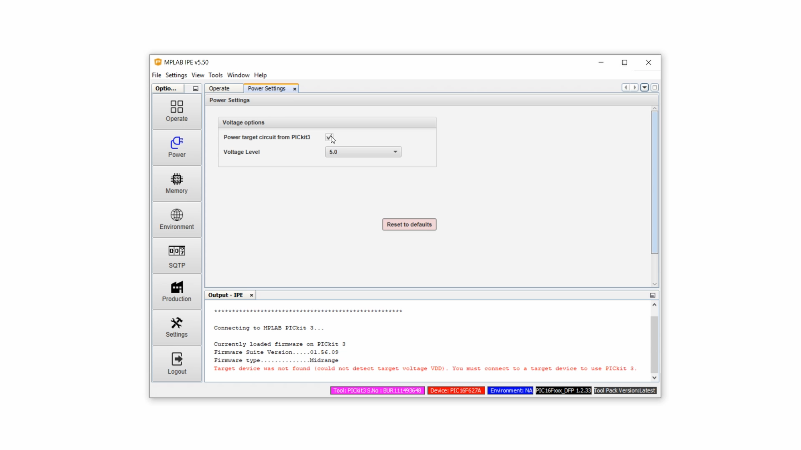
This way the PIC is powered by the PICkit3 during programming, which I find very convenient because we don't need to add an external power supply this way.
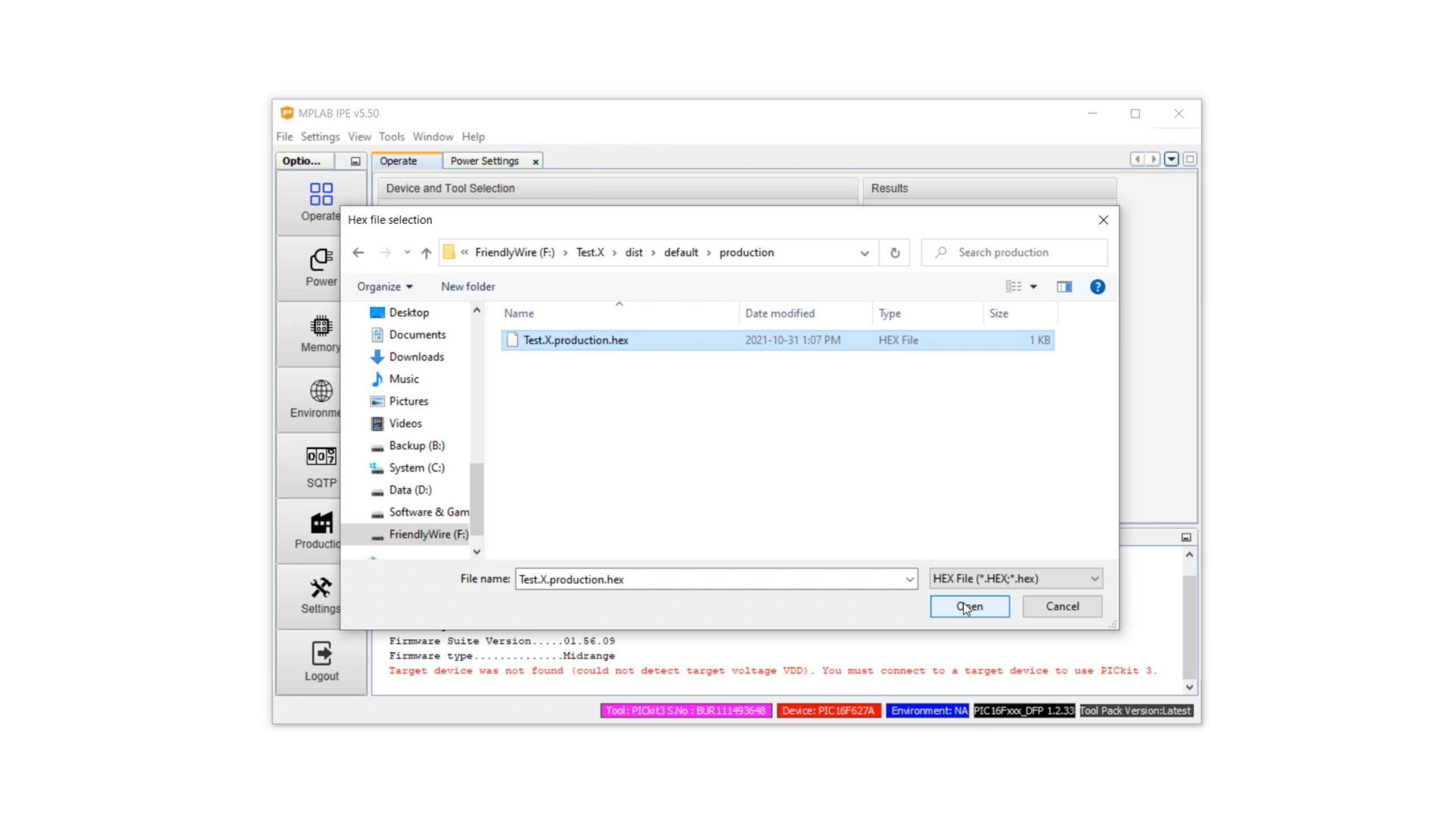
Now, click back to the Operate window, click on Browse in the Hex-File line, navigate to the .hex-file that we compiled earlier in step 3, and then click on Open:
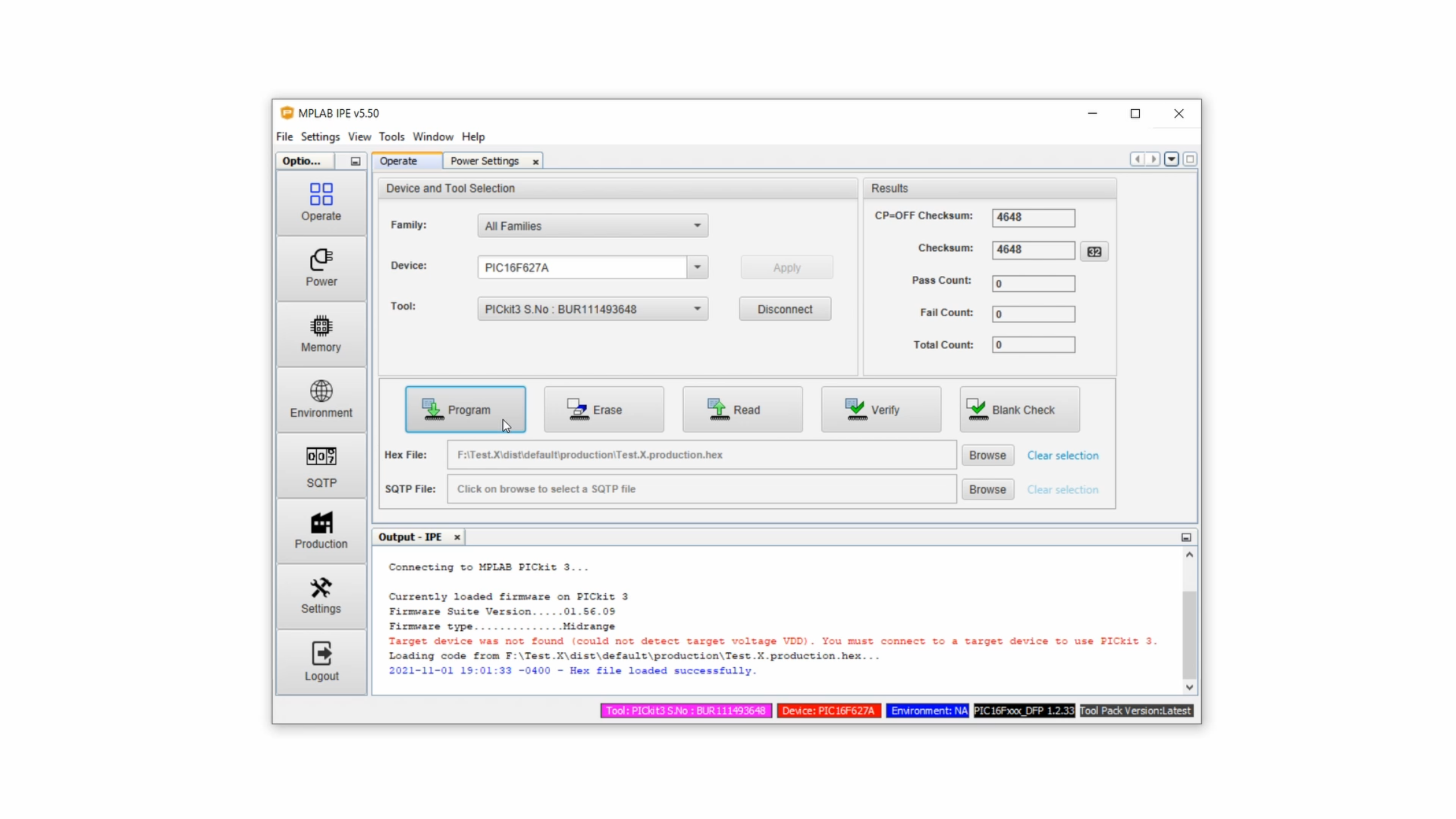
In the prompt at the bottom it should say “Hex file loaded successfully.” Click on Program and now the PICkit3 is sending this .hex-file onto the PIC microcontroller. This process is also called “flashing” sometimes. The PICkit3 has some LEDs that should start blinking at this point to indicate the data transfer.
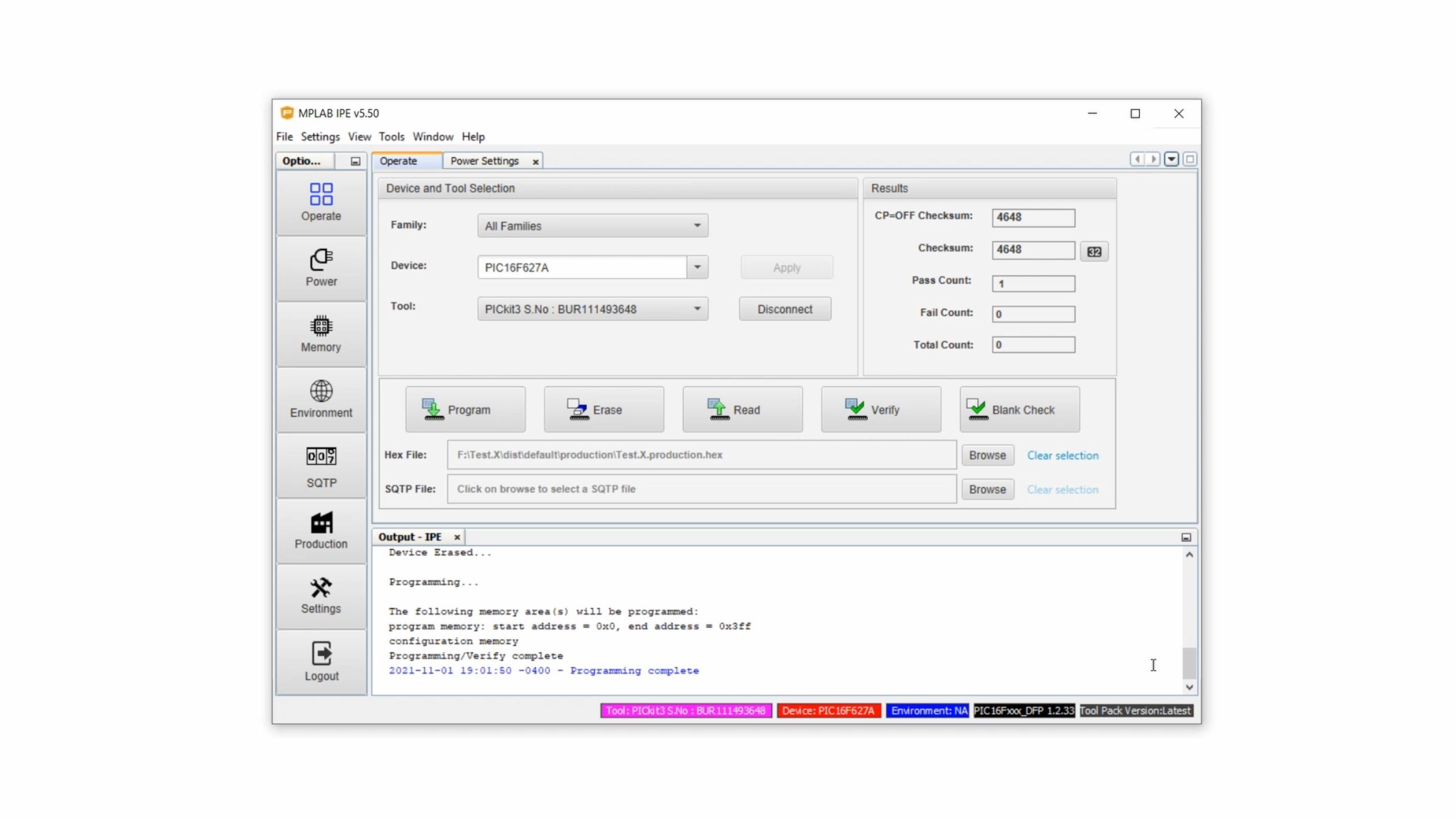
And after a few seconds it should say programming complete” in the prompt down here and we are done:
At this point the content of the .hex-file is safely stored on our PIC microcontroller. We can remove it from the breadboard and it's ready to use in our project! Congratulations!
Common mistakes and their solutions
Okay, so the first time I tried this it didn't work. And even today, after doing this literally hundreds of times, it still sometimes just doesn't work. So here is a list of things to look out for that have helped me out a lot in the past.
- Double check your wiring, and if possible use colored wires which makes it a lot easier. I know this sounds kinda obvious, but, based on my own experience: it happens.
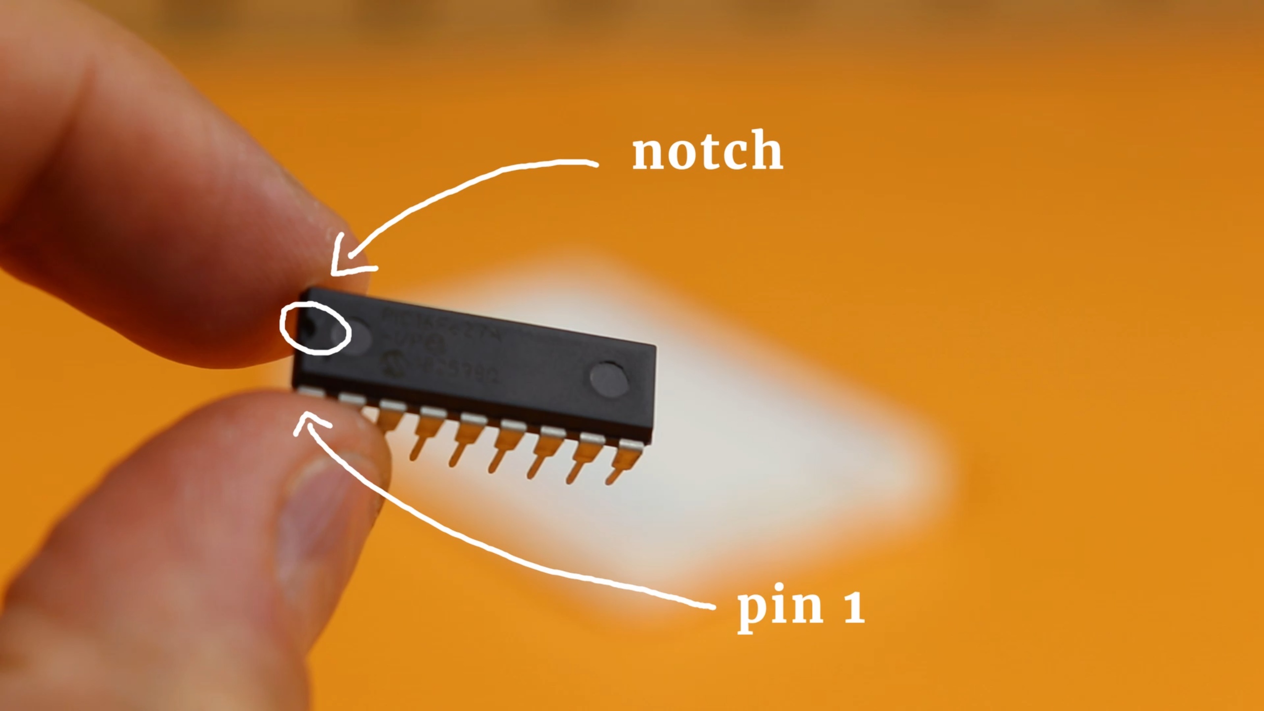
- Make sure you don't have the PIC microcontroller connected upside down. PIC microcontrollers have a notch that tells you where pin 1 is located, but sometimes it can be a bit hard to see:
- Also make sure you know where pin 1 of the PICkit3 is, it's the pin close to the white triangle.
- Some breadboards can be unreliable, so make sure that all contacts are stable. Wiggle the wires a little bit and see if it is a tight connection. If the wires comes out very easily, chances are the connection is not good.
- The same goes for the fit on the PICkit3 side. Some connectors are a bit too thin and fit very loosely in the PICkit3 connector. If they come out very easily, again chances are the connection is not good.
- Your USB port where you plugged in the PICkit3 may not have enough power! This is the error message:
Sometimes, often on laptops, this can be a big problem, especially when there are LEDs connected to your microcontroller that draw extra current. In this case it is a good idea to go into the MPLAB IPE and disable the option power target circuit from PICkit3:
Instead, use a dedicated power supply. Simply connect it to the VDD and GND connection of the PIC microcontroller, and leave the VDD and GND connection to the PICkit3 connected as well, that is important. I find that a simple 4.5V battery pack works very well for that:
- If it still doesn't work, disconnect all external circuitry from your PIC controller. Especially when there are other things connected to the program data, clock, or master clear pins this can lead to interference that destroys the signal integrity of the programmer.
- As a last resort, try another chip of the same type. Sometimes, the Pic microcontroller may just be broken. That's why I always advise people to get at least 2, better 3 of the same microcontroller. This way you cannot just build more amazing projects, you can also use it in a case like this.
Finish line! You did it!

Congratulations, you did it!
And here is something very important: if it still doesn't work, or if any of that doesn't make sense, please don't hesitate to get in touch on social media, I will do my best to help you out.
And now, what are you waiting for? Go find a nice PIC microcontroller project and give it a go! Thank you for reading, and I will see you next time!