NE555 tutorial: three useful circuits
June 20, 2020 • tutorial
The NE555 is an extremely versatile integrated circuit that can be used for a wide variety of situations and projects. Today we will learn about what is inside an NE555, and how we can use it to build an oscillator, a timer, and a flip flop switch with a few capacitors, resistors, and of course the NE555.
What's inside an NE555?
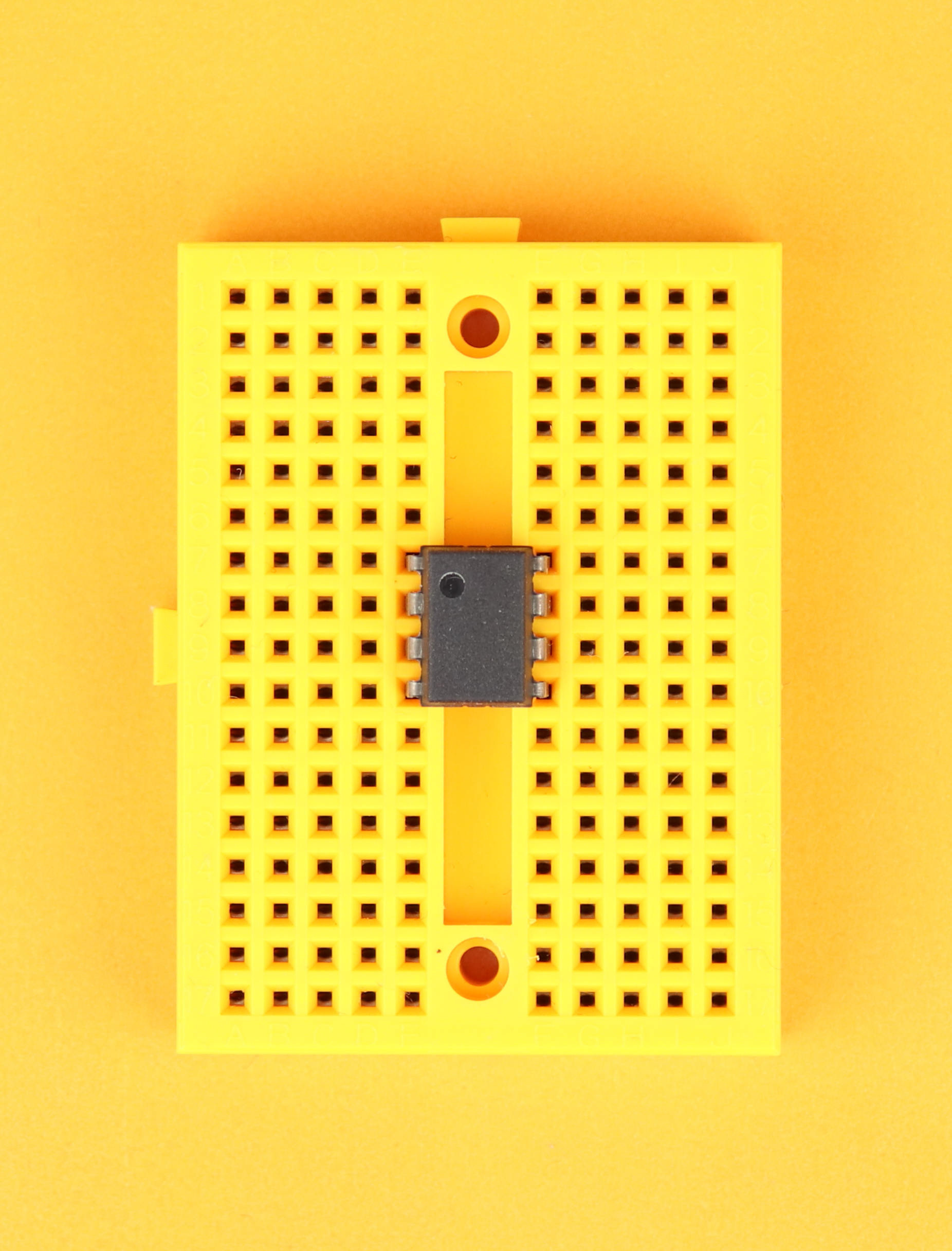
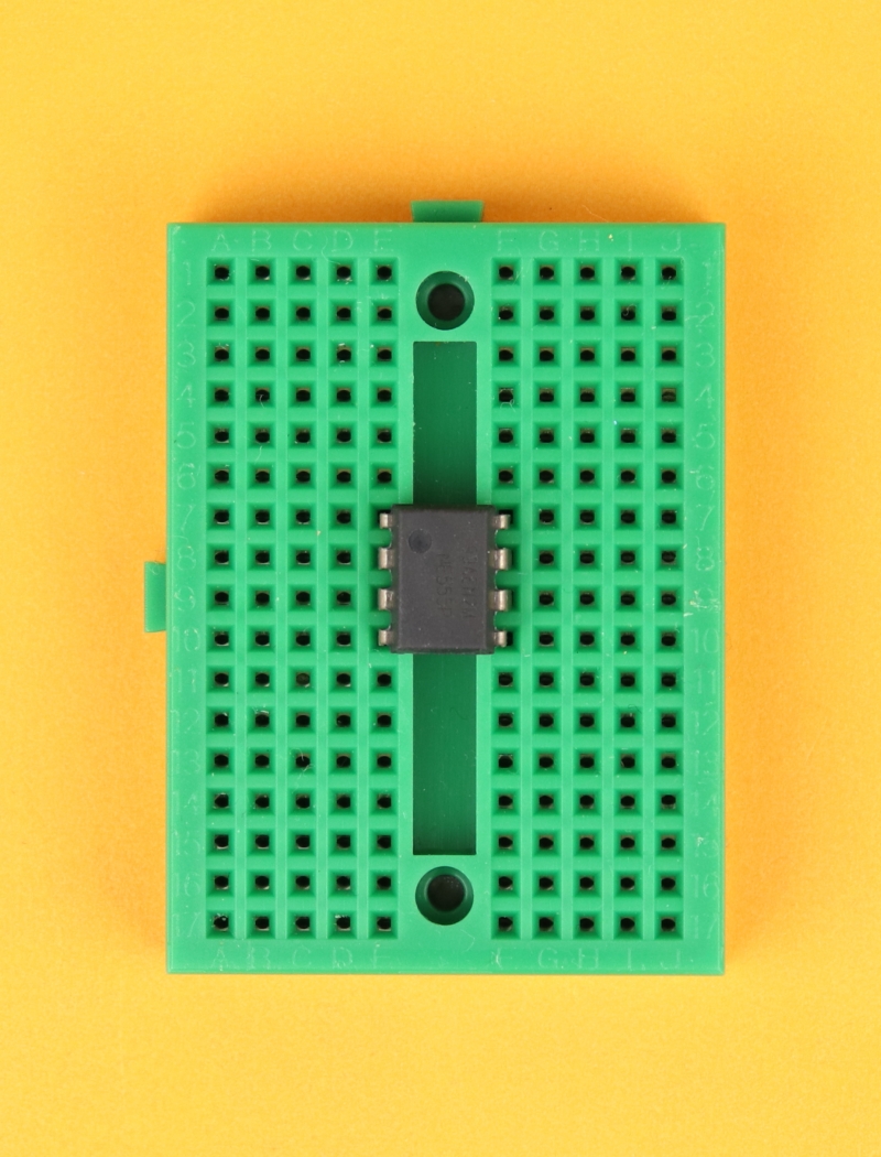
The NE555 is an integrated circuit, meaning that it combines a lot of components in a very small package. This package is called DIL8, which stands for dual-inline, and the 8 tell us that the NE555 has eight terminals. Here you can see the NE555 chip with its eight terminals:
To understand what each of these terminals do let us take a look inside:
Let's go through step by step!
- VDD and GND are the connections for the positive and negative power supply terminals. Together with the resistors R1, R2, and R3 this generates a voltage divider into three equal parts. The potential between R1 and R2 is ⅔VDD and the potential between R2 and R3 is ⅓VDD. If you use a +9V power supply, which we will do later, then these two voltages are 6V and 3V. Some people say that the three 5kΩ resistors are what gives the NE555 its name, but apparently this has been a happy coincidence and was not done intentionally.
- COMP1 and COMP2 are comparators. They have two inputs, here called + and -, and one output. Whenever the voltage at + is larger than the voltage at -, they output VDD (a logical 1), and whenever the voltage at - is larger than the voltage at +, they output 0V (a logical 0).
- RS1 is a so-called RS flip flop. Its operation is very simple: whenever S is 1 and R is 0, the output Q is set to 1 as well. Whenever R is 1 and S is 0, the output is reset to 0. When both R and S are 0, nothing happens. When both R and S are 1, the output is undefined, so we should avoid that configuration. The additional reset input overrides anything that happens at the R and S inputs. When the reset input is low, the output Q gets reset to 0, and when reset is high, the output remains unchanged.
- INV1 is a simple inverter: if its input is 1 its output is a 0, and if its input is a 0 its output is a 1 :)
- T1 is an NPN transistor. It is activated whenever Q is 0, and it is deactivated whenever Q is 1. More on that below!
Okay, now we know what the components are we can talk about the external inputs. We already talked about the power connections VDD and GND, but what do the other pins do?
- CONTROL is a reference pin that we can use to change the voltage at the - input of COMP1: we could connect it to VDD with a different resistor and therefore change the voltage. Here we don't need it, so we mostly connect it to ground with a 10nF capacitor for stability.
- TRIGGER is the - input of COMP2. Whenever its voltage is less than ⅓VDD, the output of COMP1 goes high, and the RS flip flop is set so that Q is high, too. This “triggers” the output of the NE555 to go high as well, and that's where the name of this pin comes from.
- THRESHOLD is the + input of COMP1, and it can be used to turn the output of the NE555 off. How? If the voltage at this pin exceeds the control voltage, the output of COMP1 goes from 0 to 1, which resets the RS flip flop: then, its output Q is 0, and the output of the NE555 is zero, too. It gets its name from the fact that it resets the NE555 if the voltage surpasses a certain threshold (which is ⅔VDD in this case).
- OUTPUT spits out the value of the Q output of the RS flip flop. It can drive up to 200mA and can be directly connected to small loads. It is a push-pull output, meaning that it can drive loads both against VDD and against GND.
- DISCHARGE is a very helpful pin when using the NE555 as a timer. In the standard configuration, the discharge pin is connected to ground via the transistor T1. Why? Because in the default state the output of the RS flip flop is 0, which gets inverted by INV1 and therefore drives the base of T1. This in turn connects the discharge pin to ground. If the RS flip flop is set, however, the discharge pin is floating. This pin gets its name from that fact that we can use it to charge and discharge timing capacitors, and we will talk a lot about it below :)
- /RESET overrides the RS flip flop. It is an inverted pin, which is why we call it /RESET instead of RESET. This means that if /RESET is set to 1 the NE555 works in the normal configuration (which is why in many circuits the /RESET pin is tied to VDD permanently). If /RESET is connected to GND, however, it resets the flip flop and overrides anything going on on its R and S inputs. This pin is very useful when we want to use the NE555 as a bistable flip flop and whenever we don't need the timing features.
Now that we understand the basics, let's look at three very useful circuits based on the NE555: an oscillator (“astable mode”), a timer (“monostable mode”), and a simple flip flop (“bistable mode”). Don't worry when you still have some questions at this point, I know it's a bit abstract. I hope that after looking at some applications it will become much clearer. Let's go! :)
NE555 as an oscillator (“astable” mode)
One of the most common uses of the NE555 is as an oscillator that provides a periodic ON/OFF signal that you can use to make an LED blink or use as a clock signal for digital circuits. It is also called “astable” because it does not have a stable state: it keeps switching between on and off! This is the schematic:
Okay, let's take a closer look now and figure out how it all works:
- When the circuit is first powered on the capacitor C1 is uncharged, which means that the voltage at the TRIGGER pin is zero. This sets the internal flip flop and turns on the output, and disables the discharge transistor.
- The capacitor C1 is now charged through resistor R1 and diode D1, and the voltage at the TRIGGER pin soon exceeds ⅓VDD, but nothing happens yet. Only when the voltage at C1 exceeds ⅔VDD at the TRHESHOLD pin the internal flip flop is reset, turning the NE555's output off and enabling the discharge transistor.
- The capacitor C1 is now discharged through resistor R2 and diode D2, and the voltage at C1 decreases. If it falls below ⅓VDD, the TRIGGER pin will again set the NE555's internal flip flop to 1. The capacitor is no longer discharged and can therefore be charged through R1, and the loop begins all over again.
- The diodes D1 and D2 are there so that the capacitor charges only through R1 and only discharges through R2. This way, the on and off times can be adjusted independently, which can be very convenient.
LED1 blinks on and off, and the on-time and off-time are determined by the capacitor C1 as well as the resistors R1 and R2. You can calculate them like this:
In our example, R1 = R2 = 10kΩ and C1 = 22μF. This means we need to substitute 10 and 22 in the formula, which gives us ton = toff = 152ms. This means the blinking frequency is around 6.5Hz.
Now that we understand how the circuit works, let's build it on a breadboard! Here is what you need:
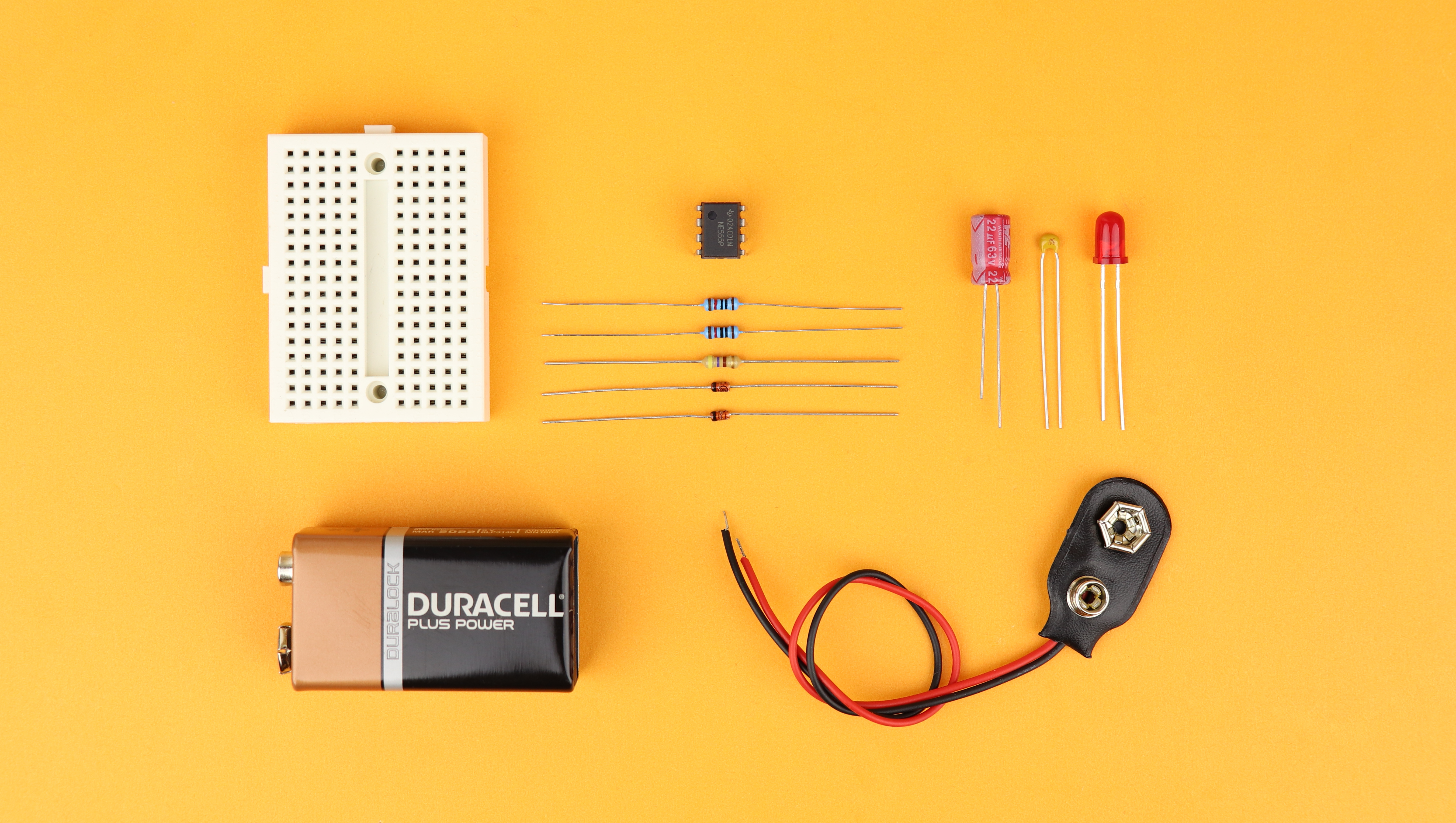
You can find a detailed list of these components in the resources box. Let's build the circuit!
-
-
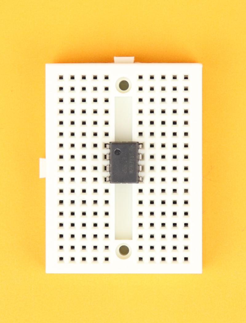
Step 1
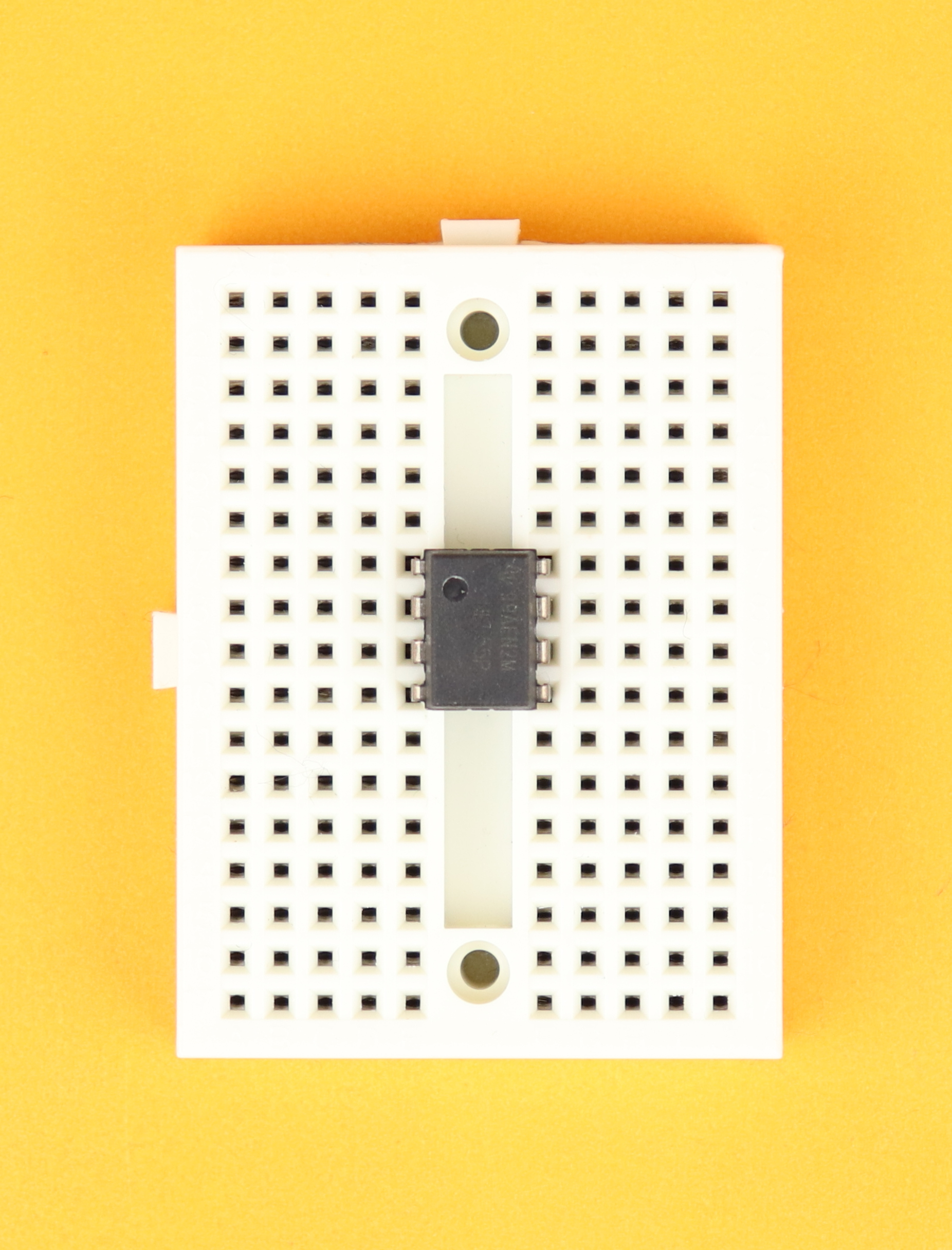
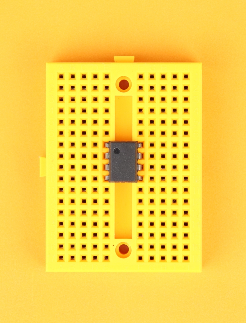
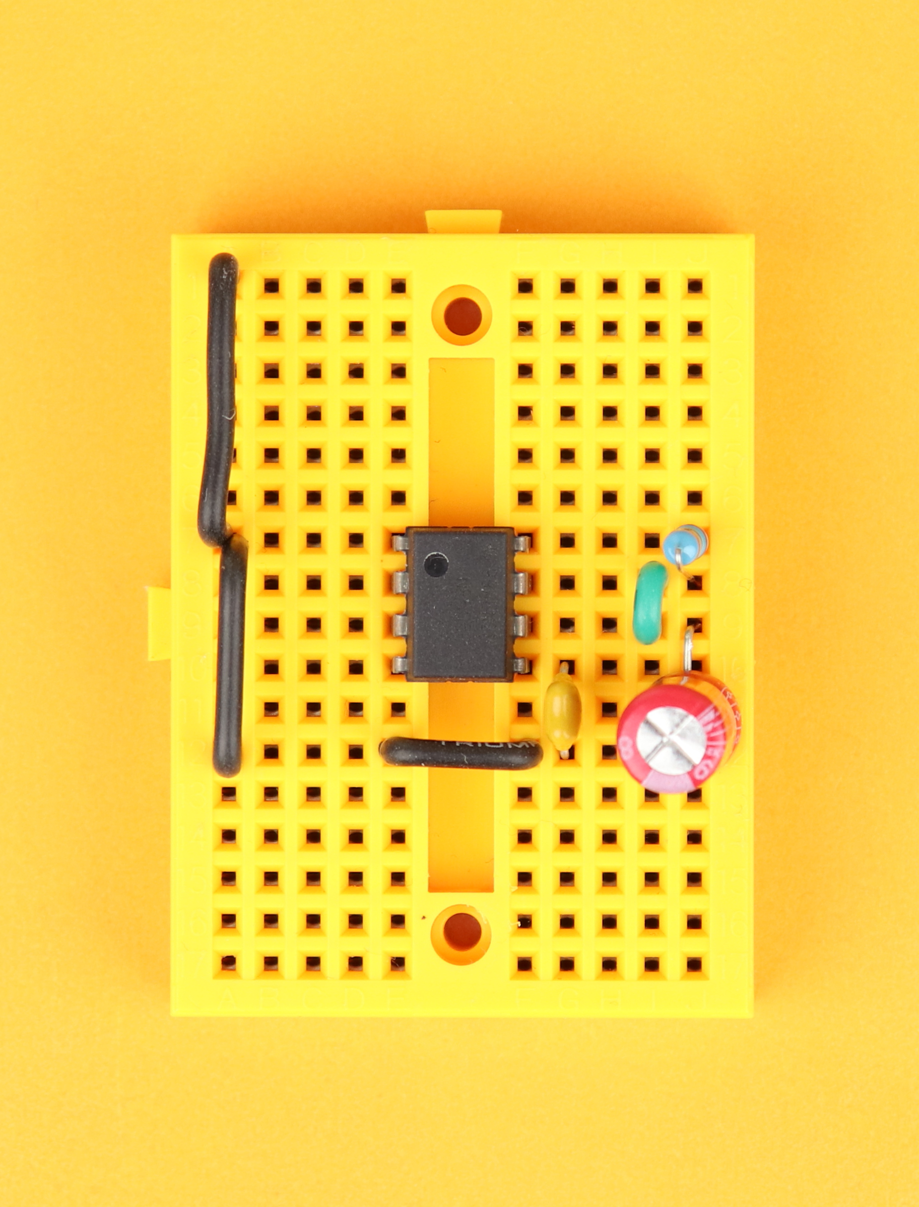
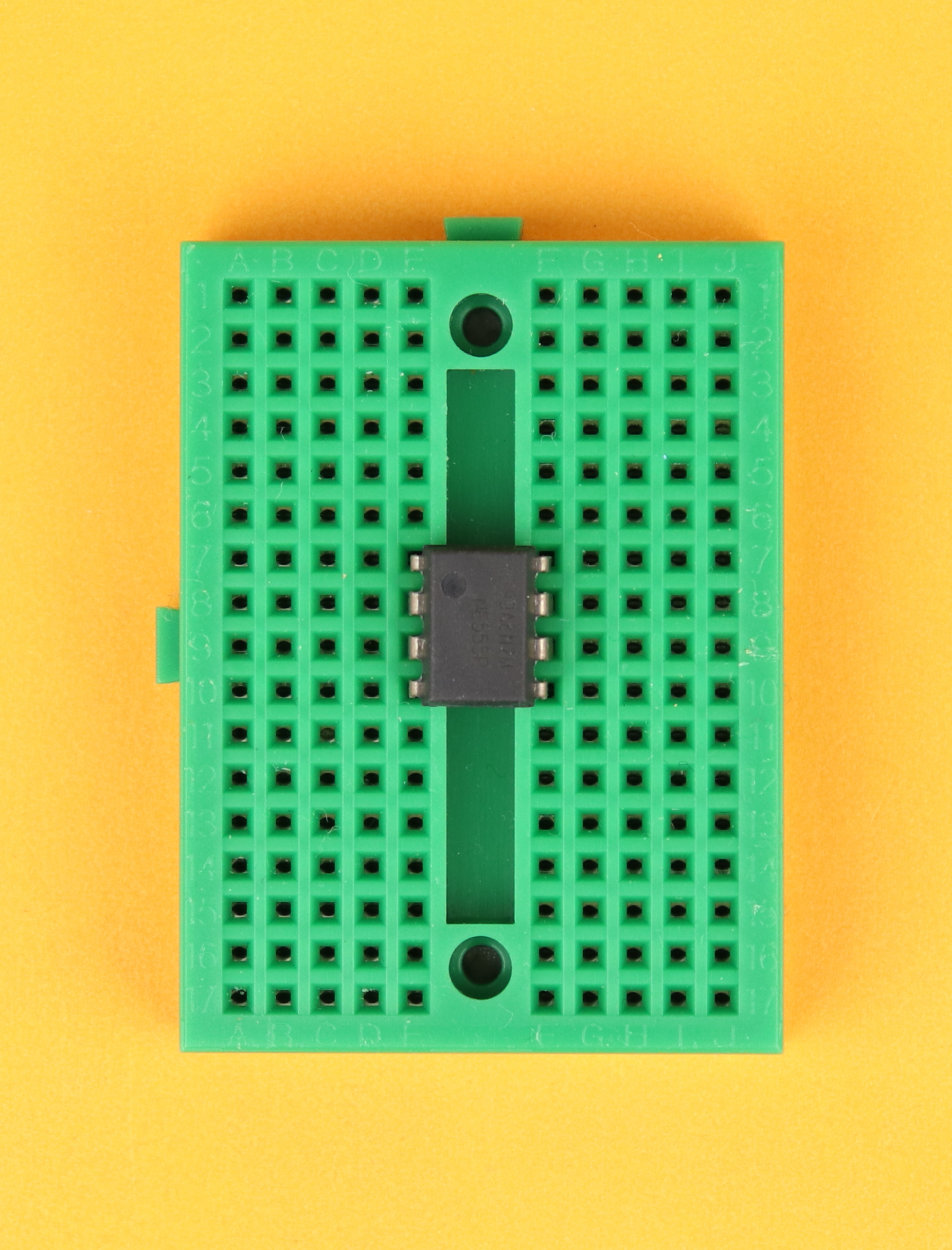
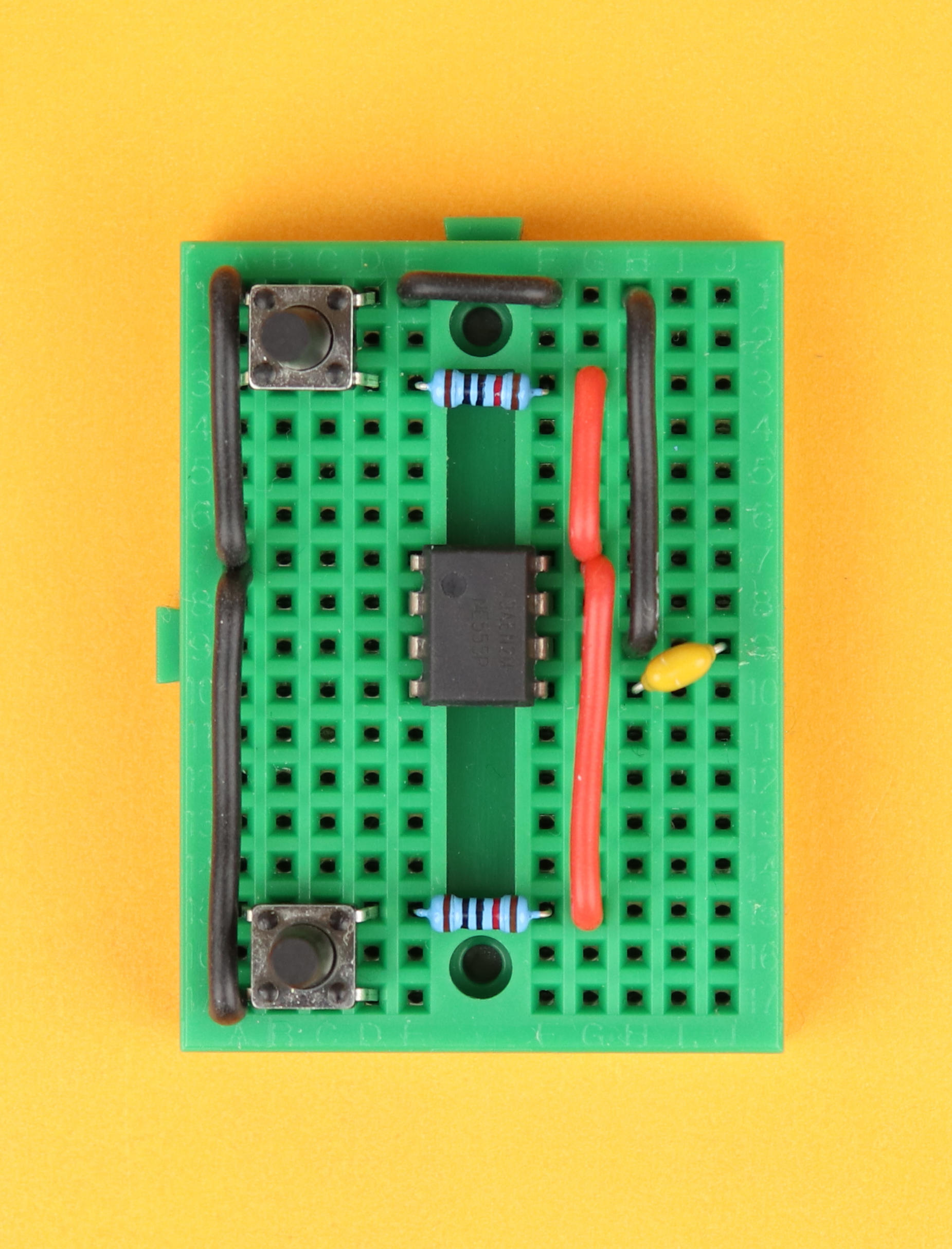
Place the 170-pin breadboard in front of you, with row 1 facing up, and insert the NE555 in row 7 with its notch facing to the top left.
-
-
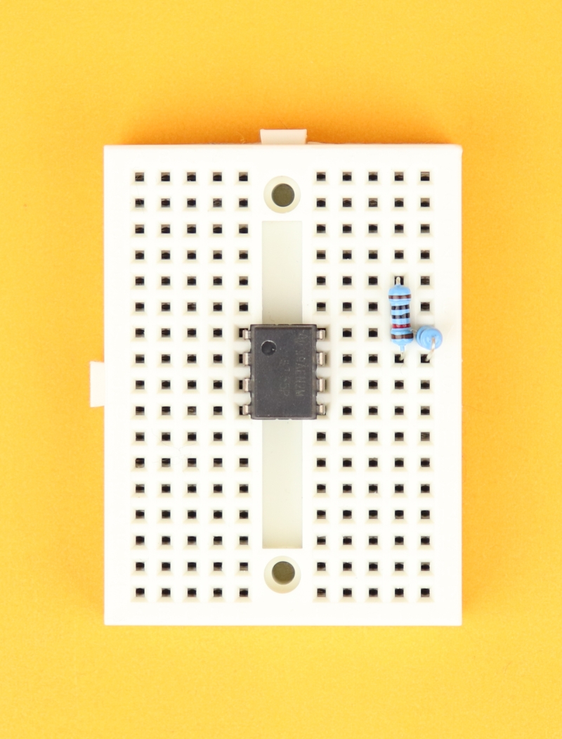
Step 2
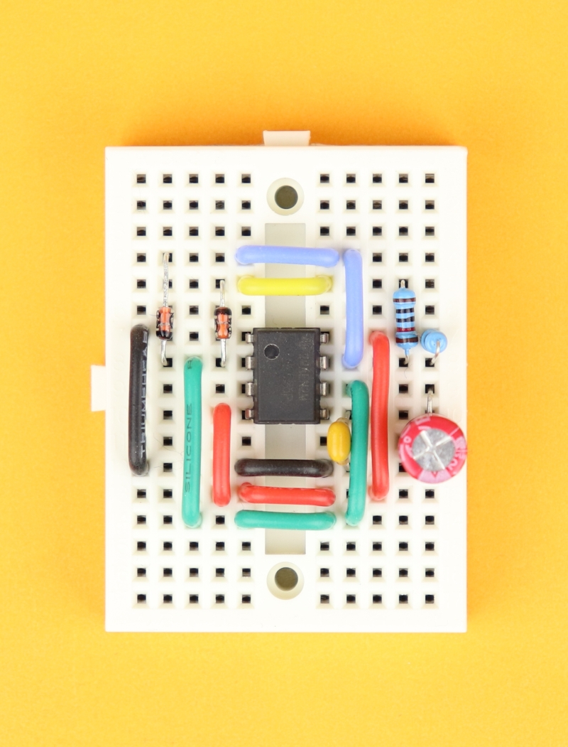
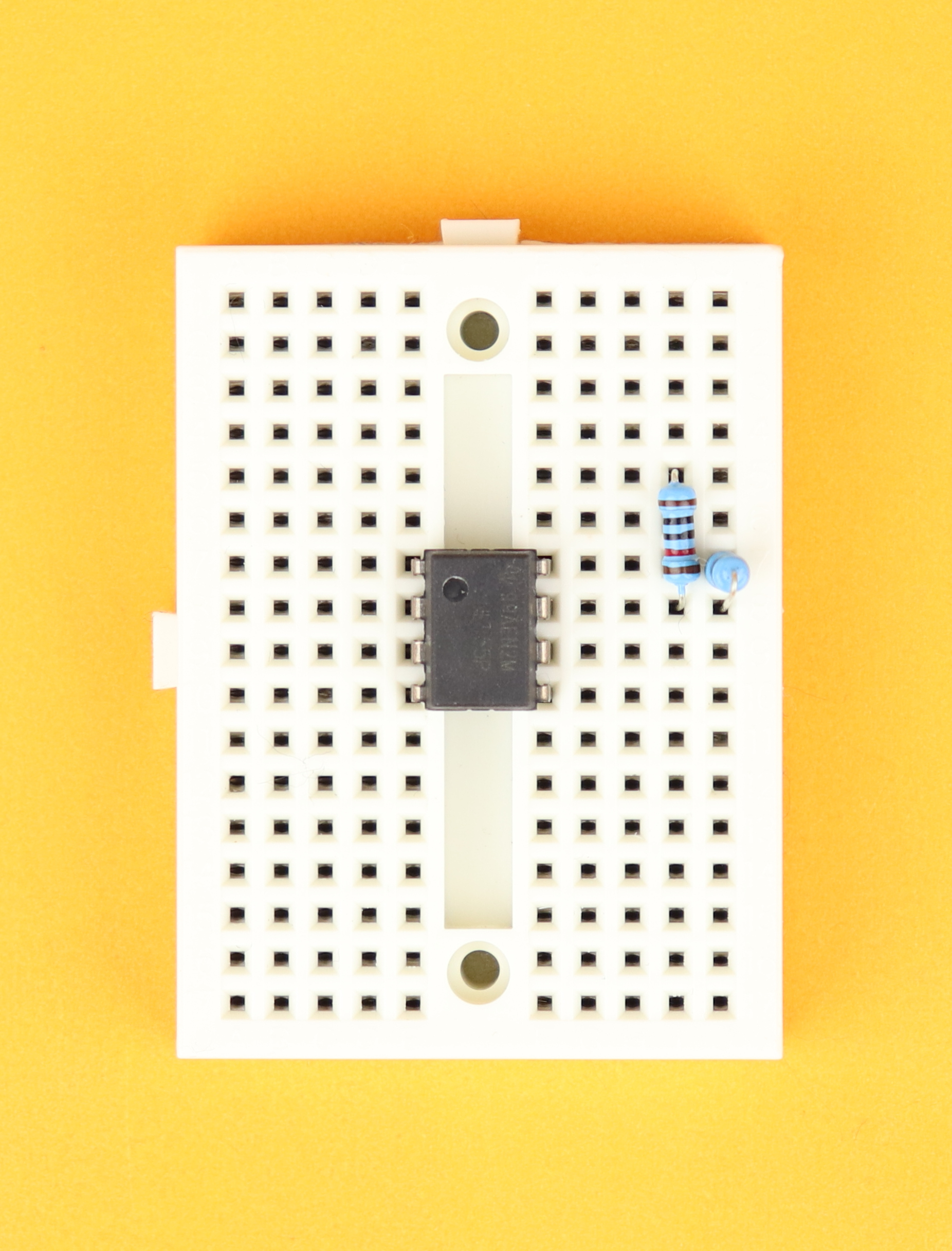
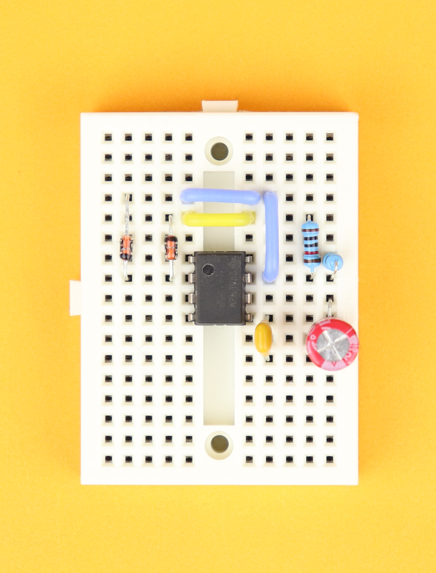
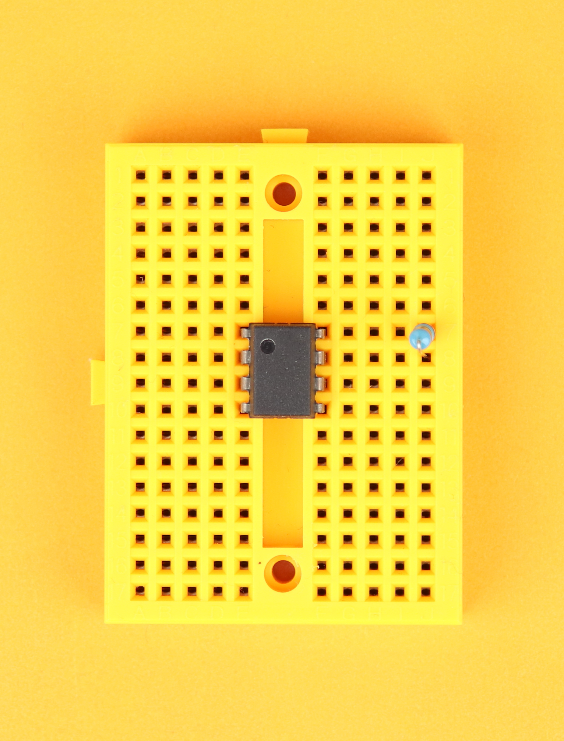
Insert a 10kΩ resistor between pins 7 and 8. Connect another resistor to pin 7 and insert its other terminal above, in row 5.
-
-
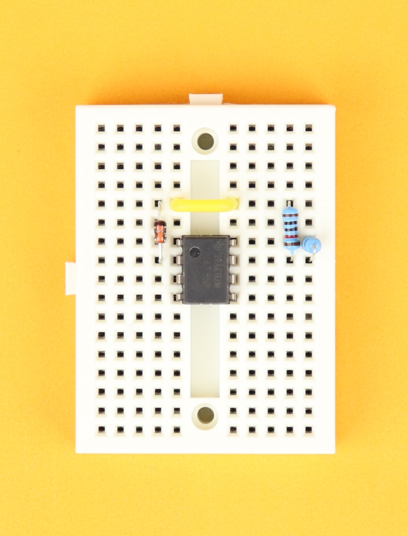
Step 3
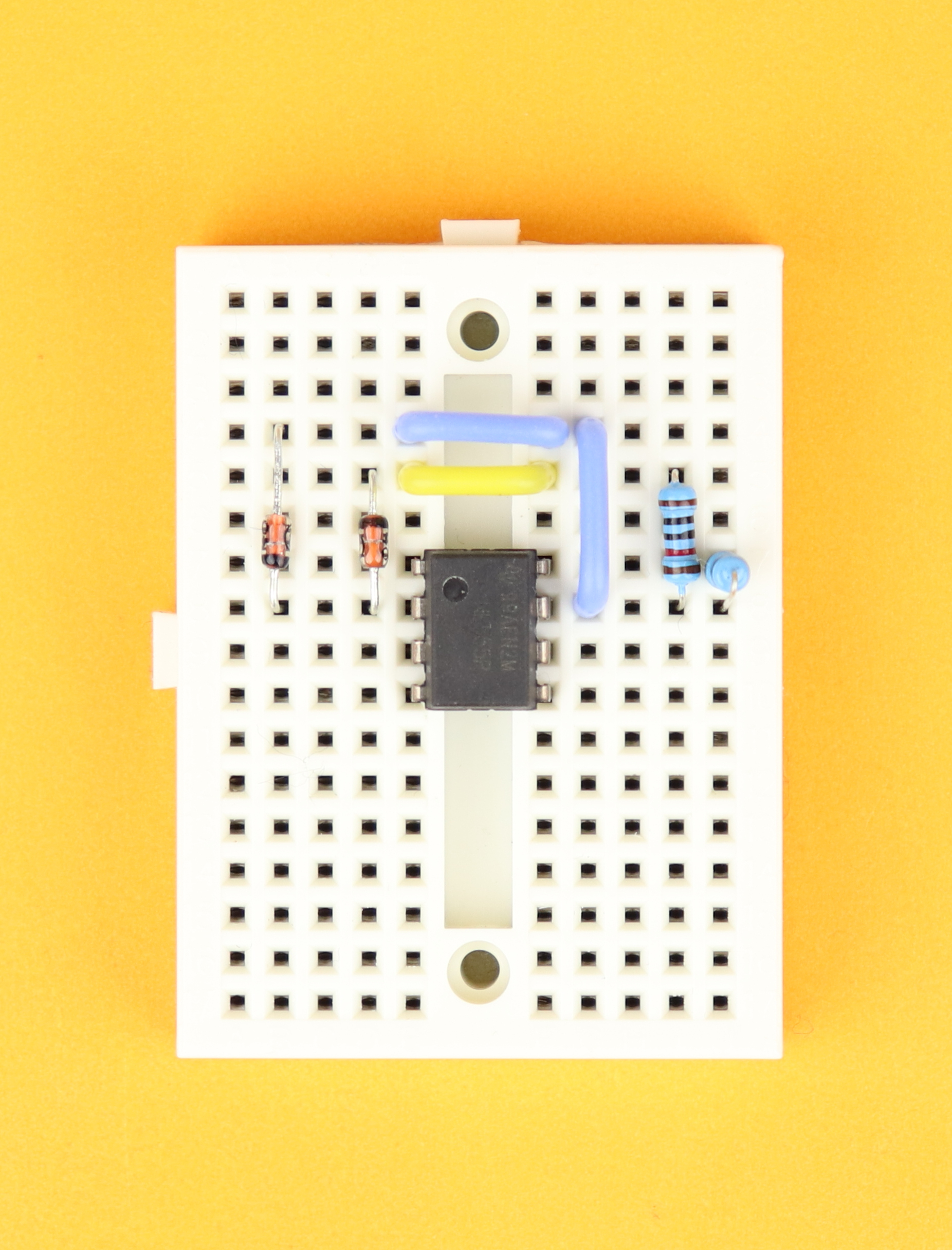
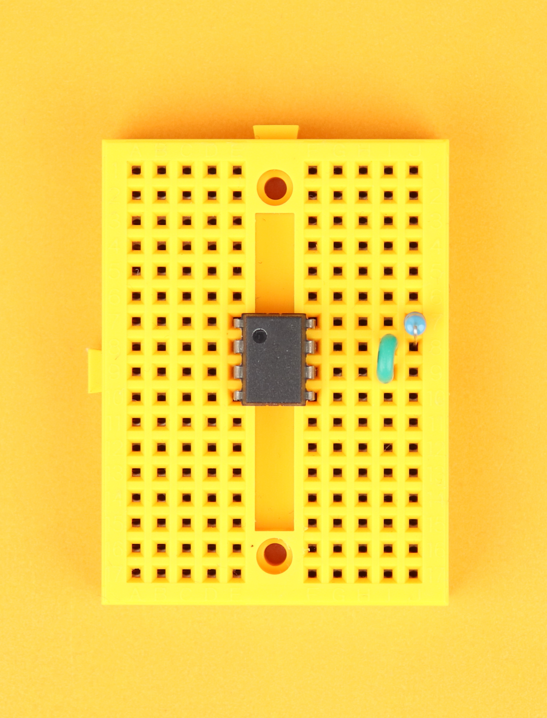
Connect row 5 on the right with row 5 on the left with the yellow wire, and insert an 1N4148 diode between row 5 and pin 2 of the NE555. Make sure that the diode's cathode (the black ring) points up.
-

-
Step 4
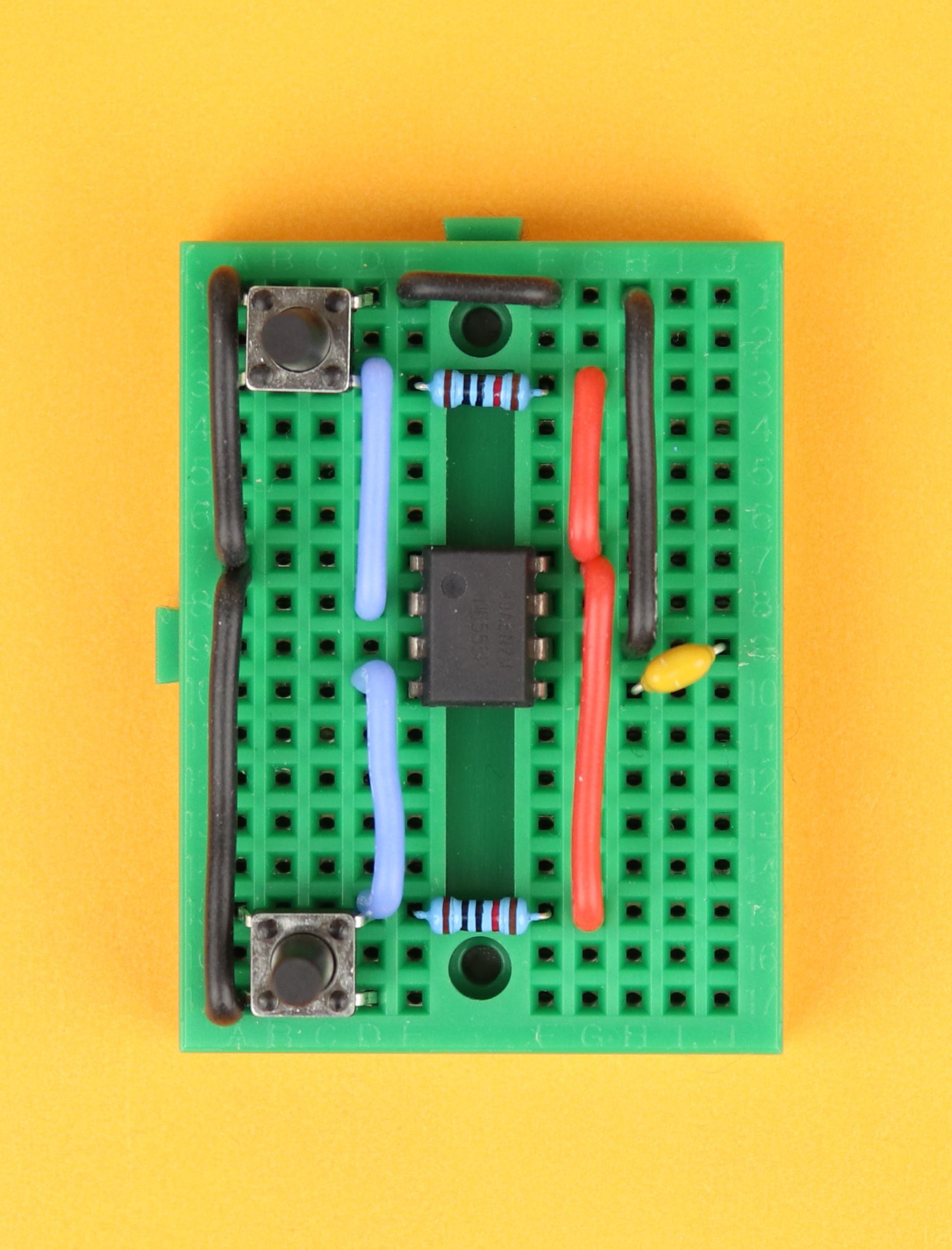
Using blue wire, connect pin 7 to row 4 on the right, connect row 4 to the left side, and then insert another 1N4148 diode between row 4 on the left and pin 2 of the NE555. Make sure that the diode's cathode (the black ring) points down.
-

-
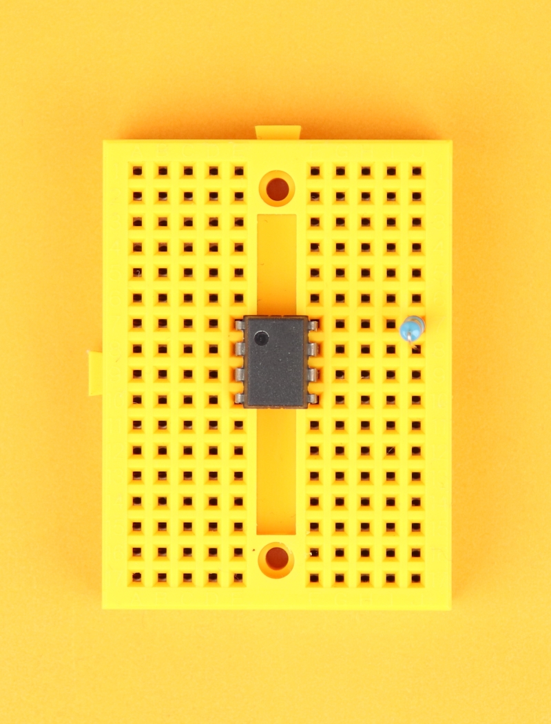
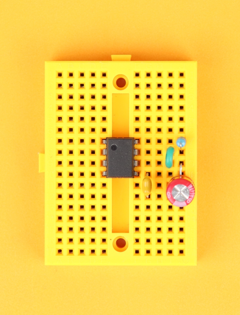
Step 5
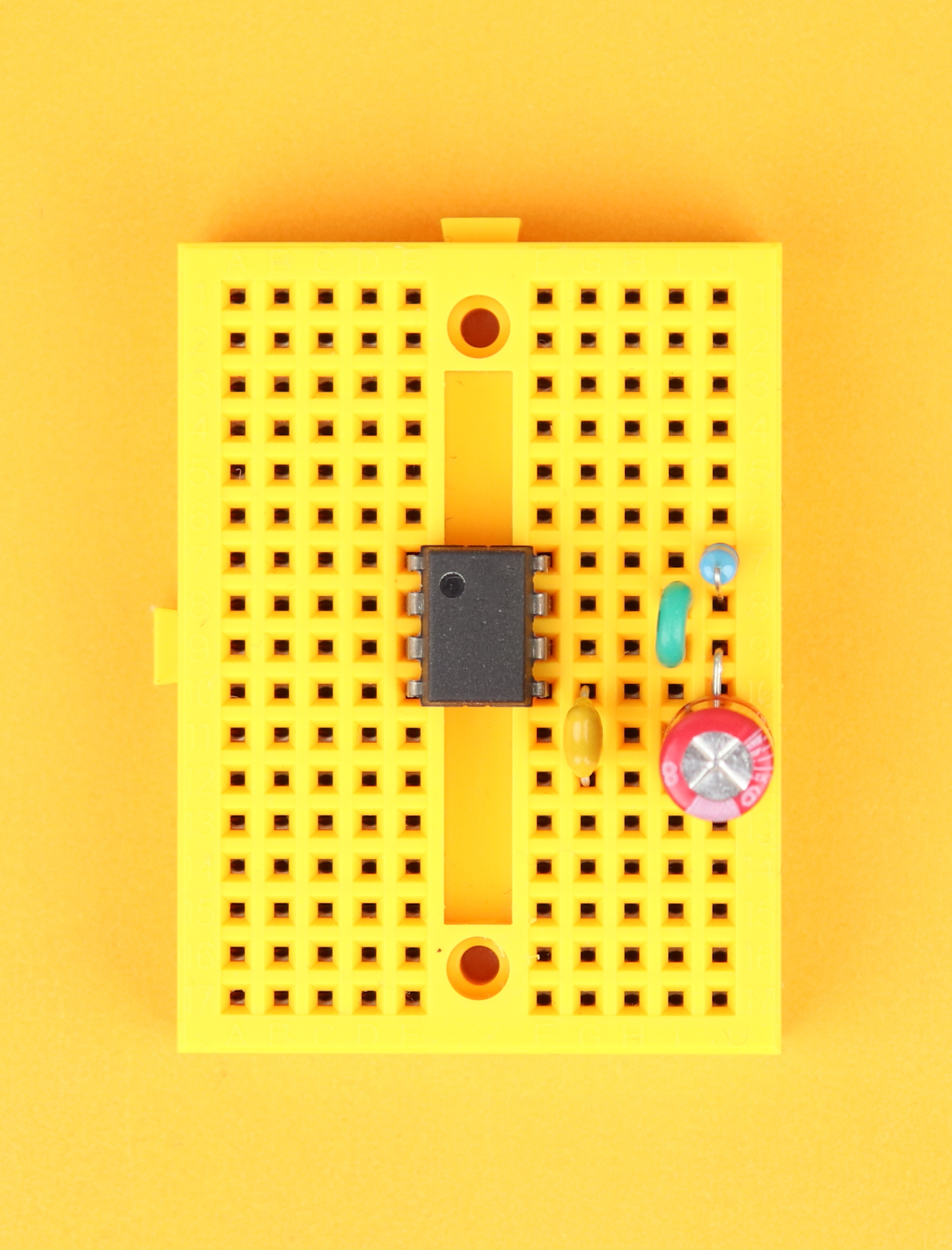
Insert the 22μF capacitor between pin 6 and row 12, and make sure the negative terminal of the capacitor is connected to row 12. The negative terminal of electrolytic capacitors is usually highlighted with a big minus sign. Then, insert the 10nF capacitor between pin 5 and row 12, and this capacitor can be plugged in either way.
-

-
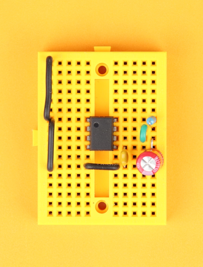
Step 6
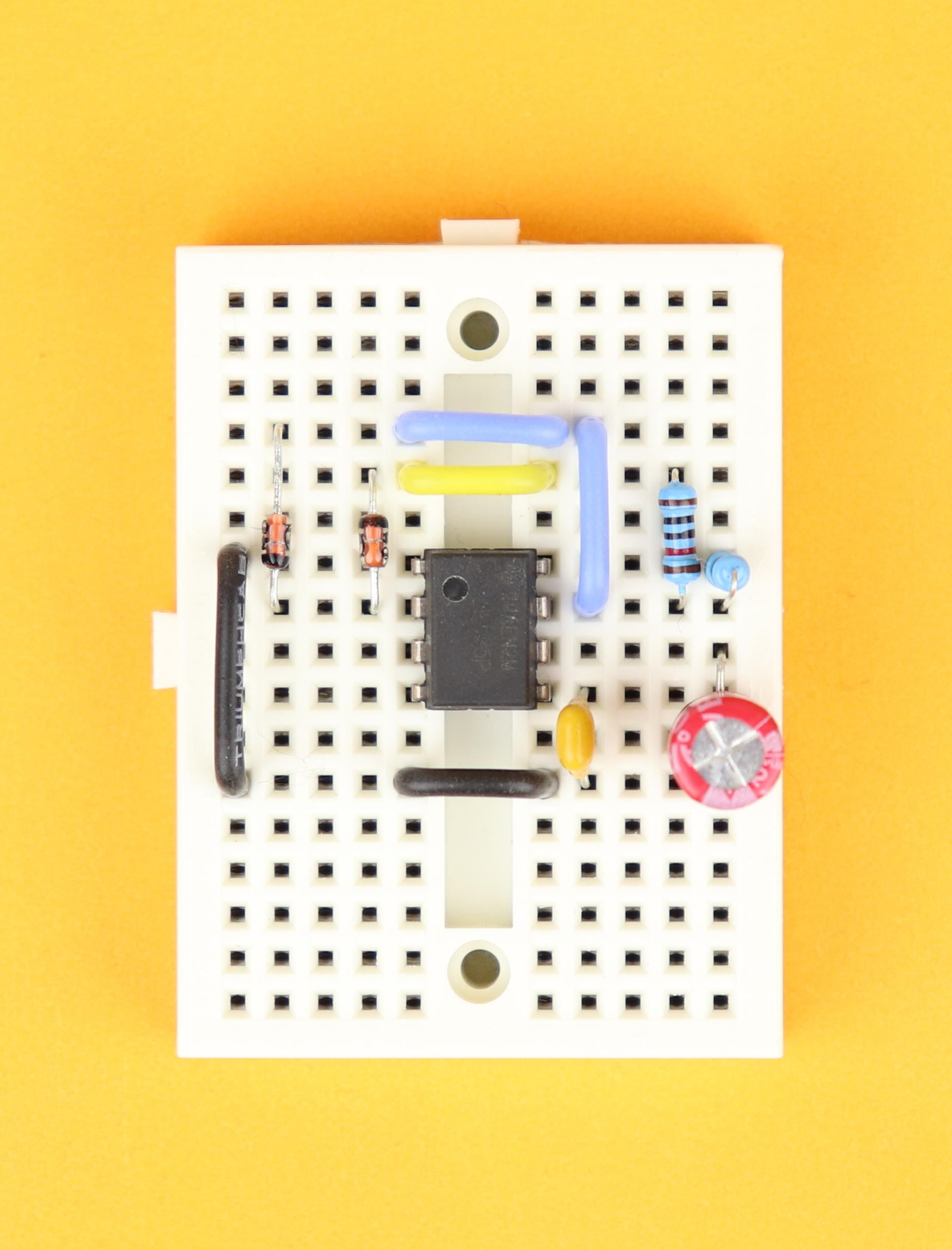
Connect row 12 on the right with row 12 on the left using the black wire, and then connect row 12 on the left to pin 1. These black wires serve as our ground rail.
-

-
Step 7
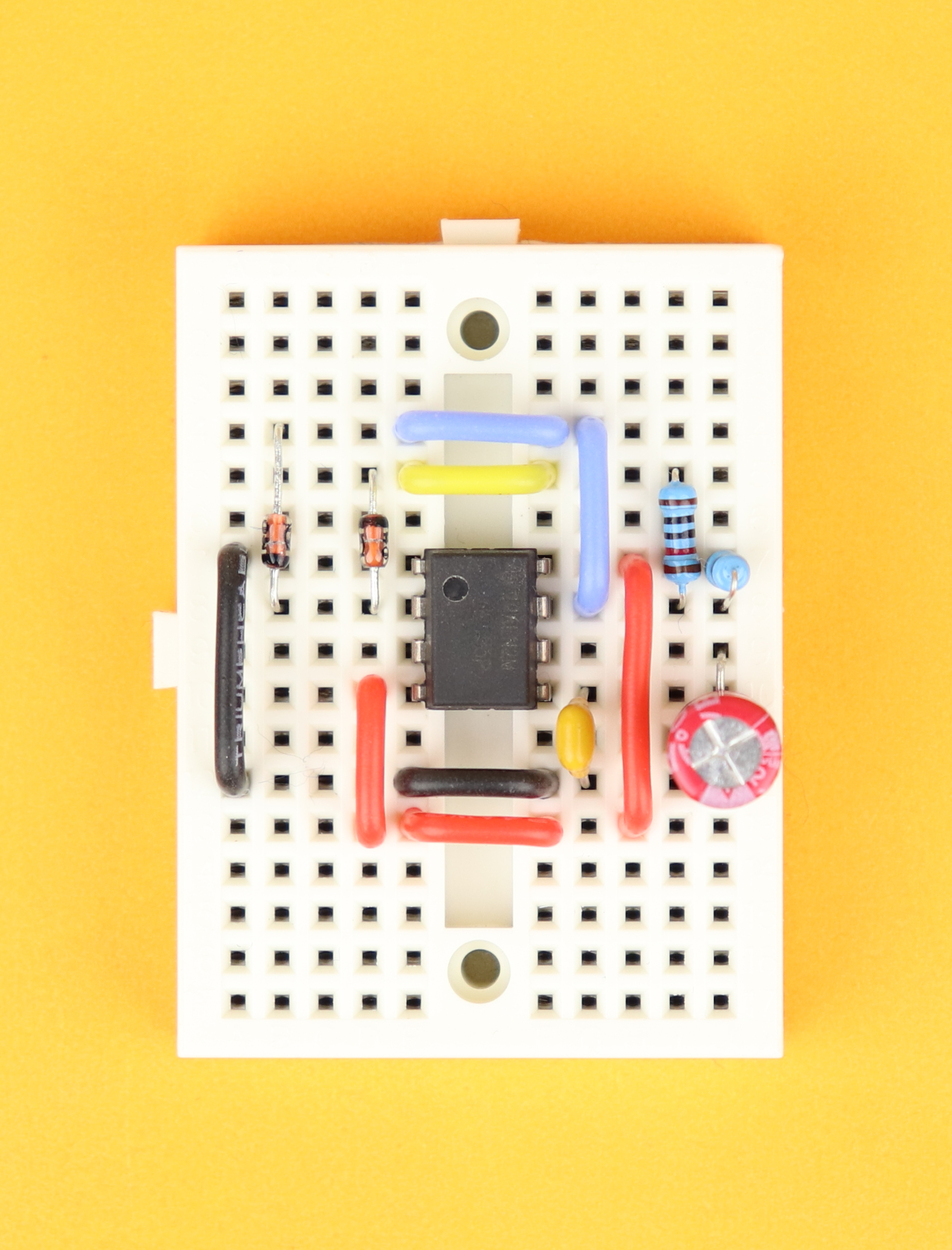
Using the red wire, connect pin 8 on the right with row 13 on the right, then connect row 13 on the right with row 13 on the left, and finally connect row 13 on the left with pin 4 of the NE555. These red wires serve as the VDD rail.
-
-
Step 8
With the green wires, connect pin 6 to row 14 on the right, then connect row 14 on the right to row 14 on the left, and then connect row 14 on the left to pin 2 of the NE555.
-
-
Step 9
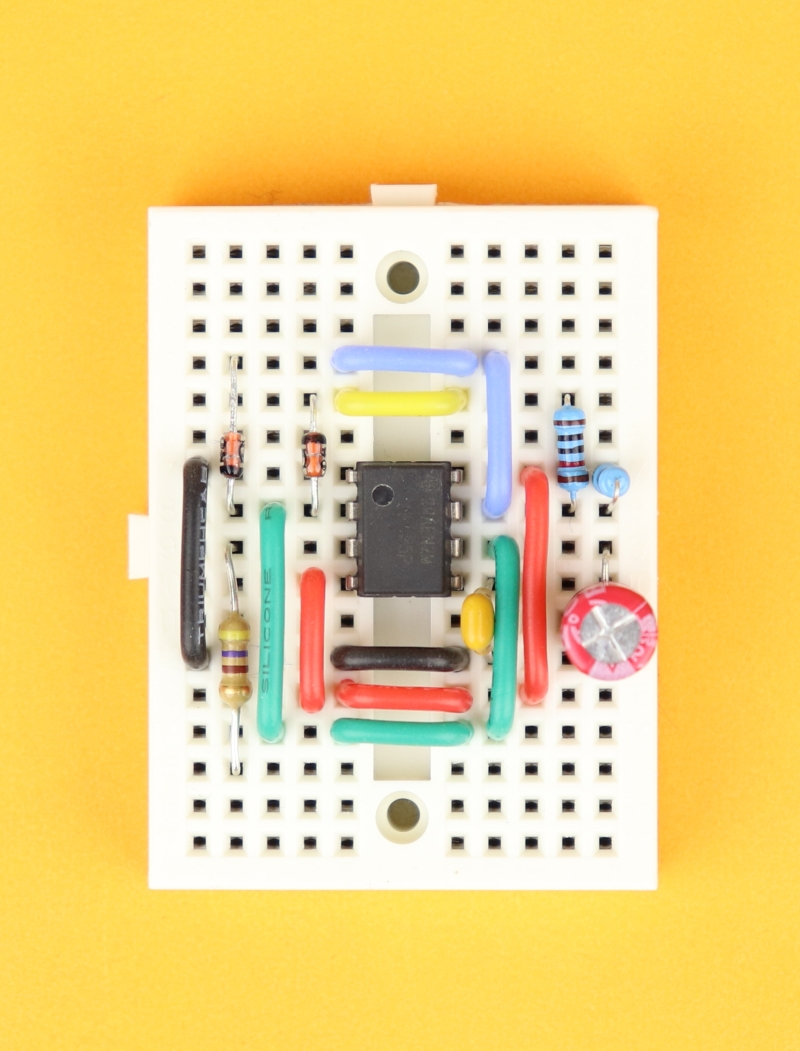
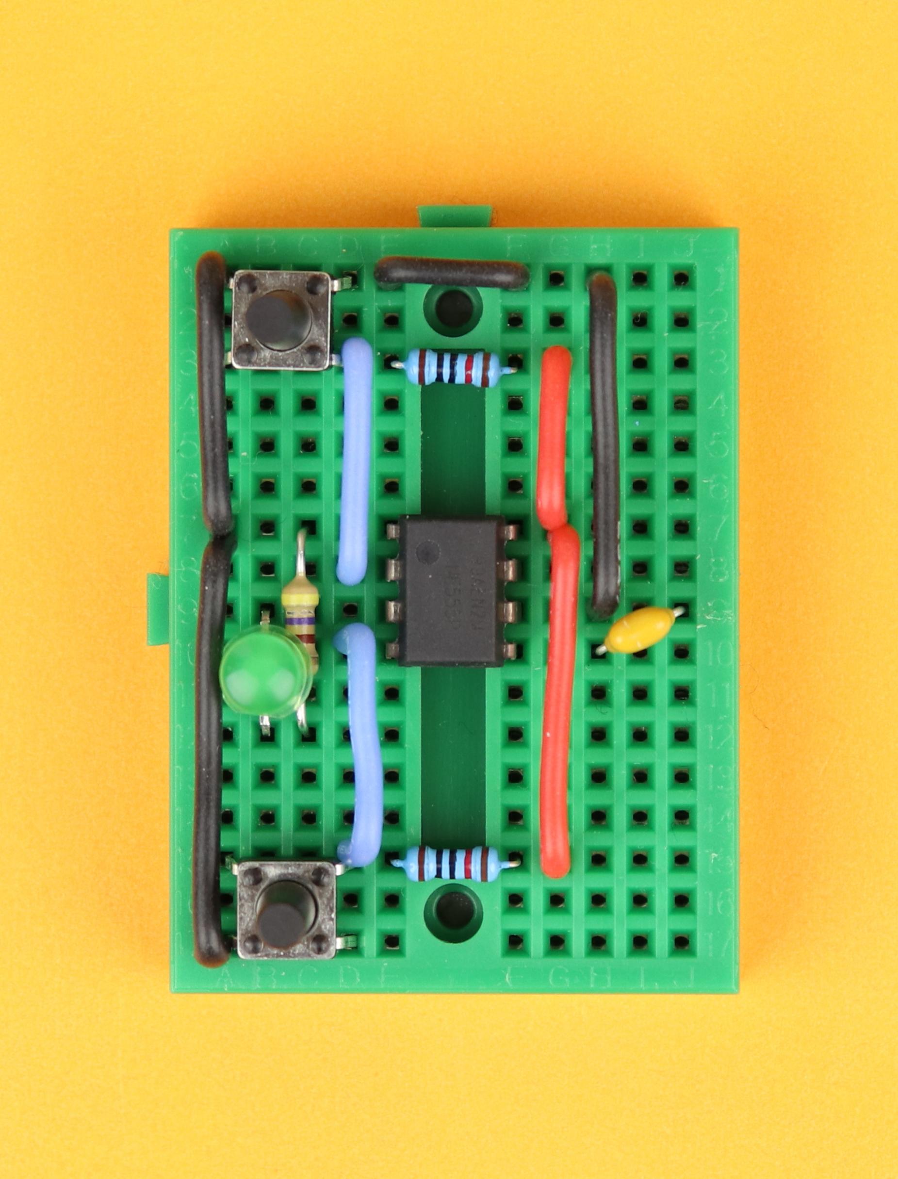
Insert the 470Ω resistor between pin 3 of the NE555 and row 15.
-
-
Step 10
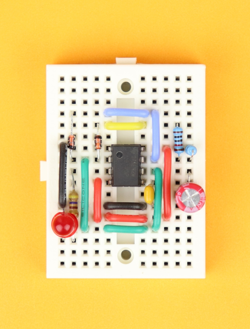
Insert the LED between rows 12 and 15 on the left. Make sure that the LED's cathode (the shorter wire) plugs into row 12, and the LED's anode (the longer wire) is connected to row 15.
-
-
Step 11
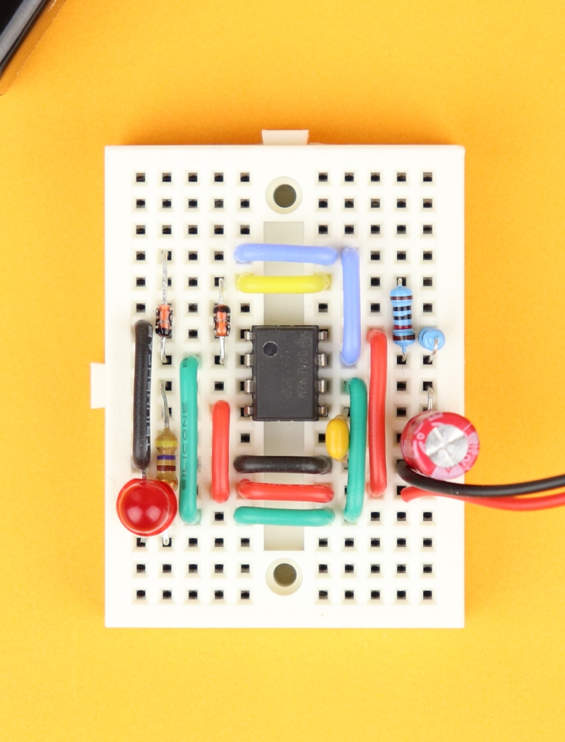
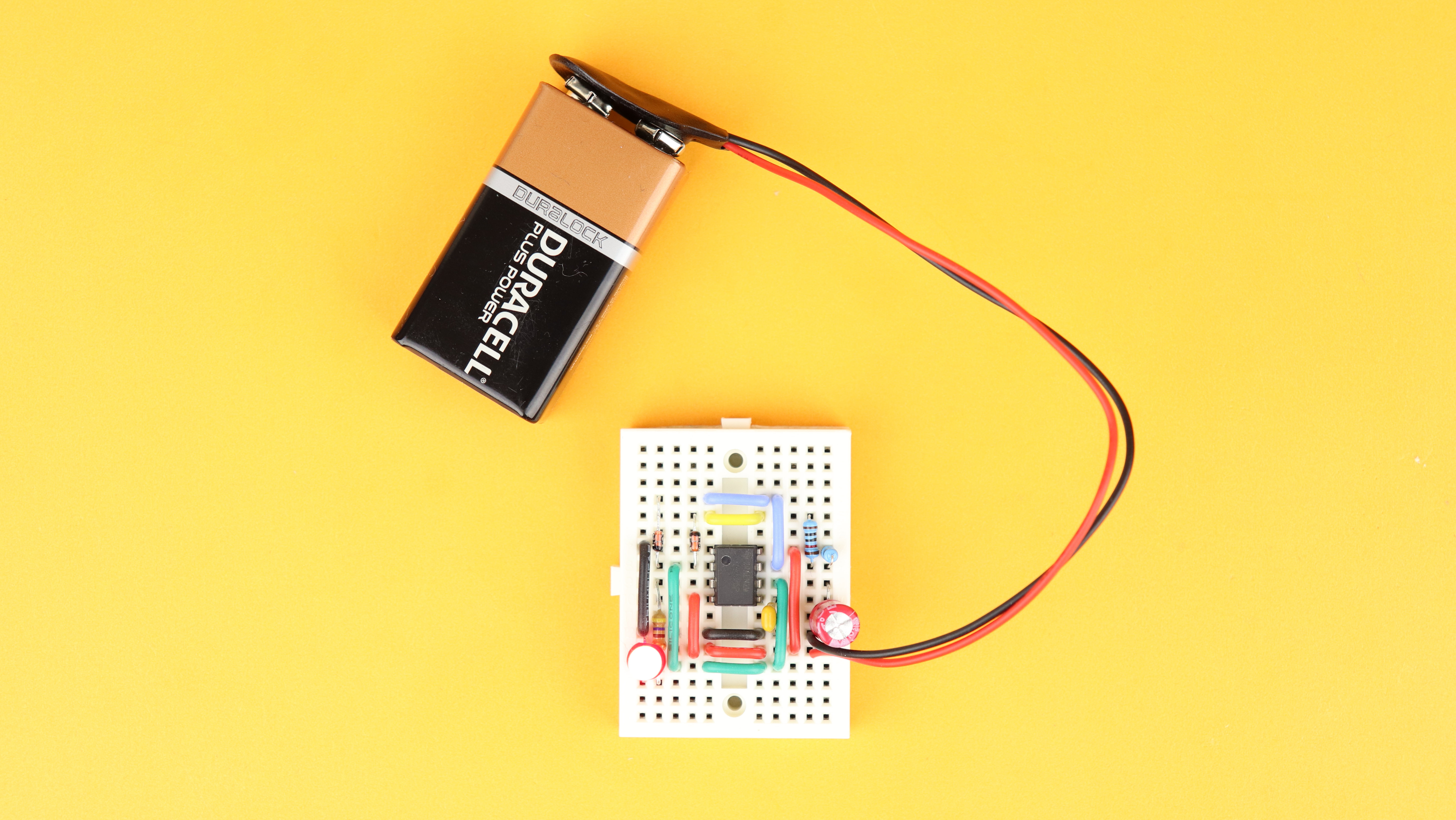
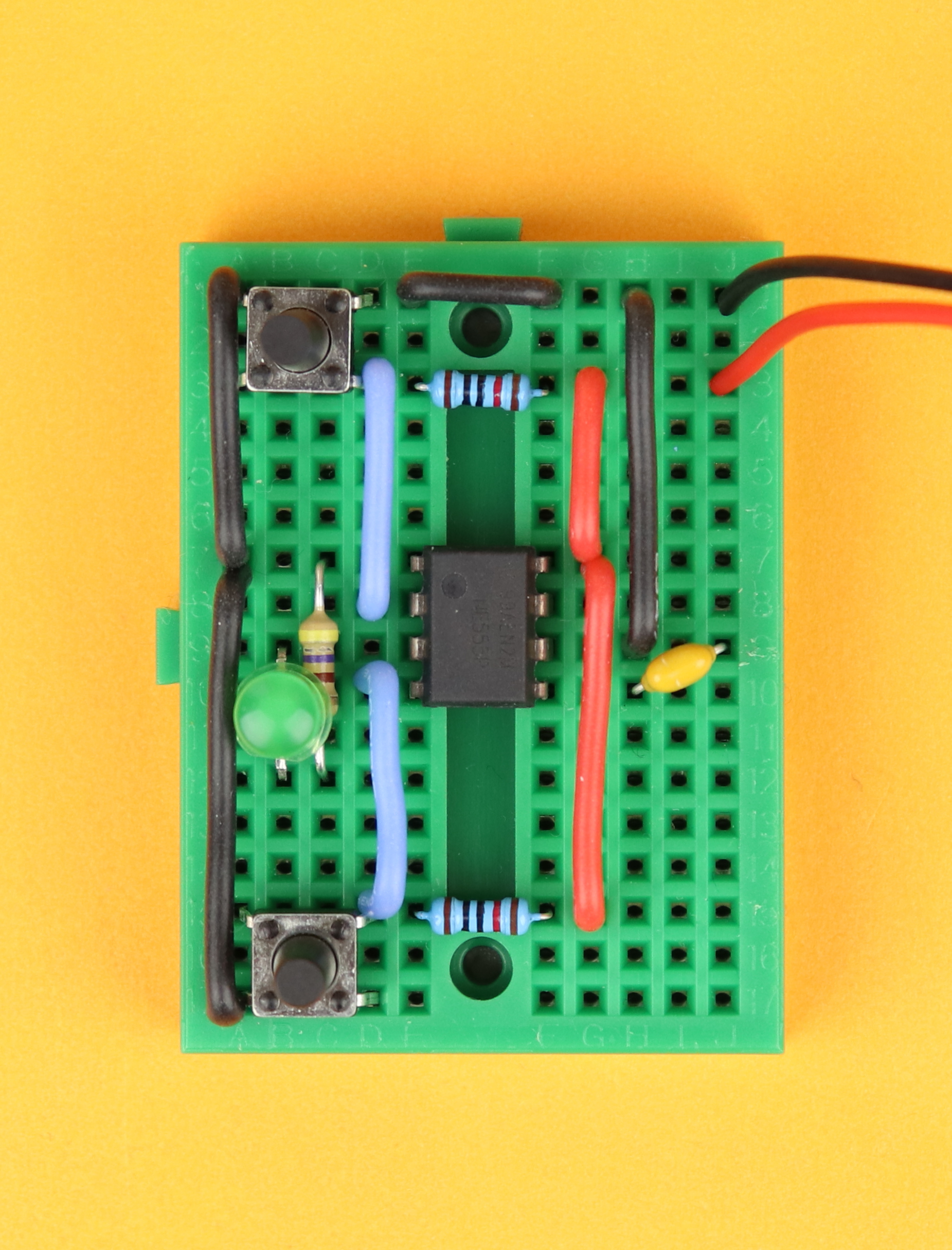
You can plug in the positive terminal of the 9V battery into the VDD power rail anywhere you want, I chose row 13 on the right. The same is true for the negative terminal of the 9V battery, it can be plugged into the ground power rail anywhere you like, and I chose row 12 on the right.
-
-
Step 12
Now you are done, and your LED should start flashing :)


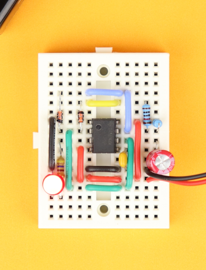
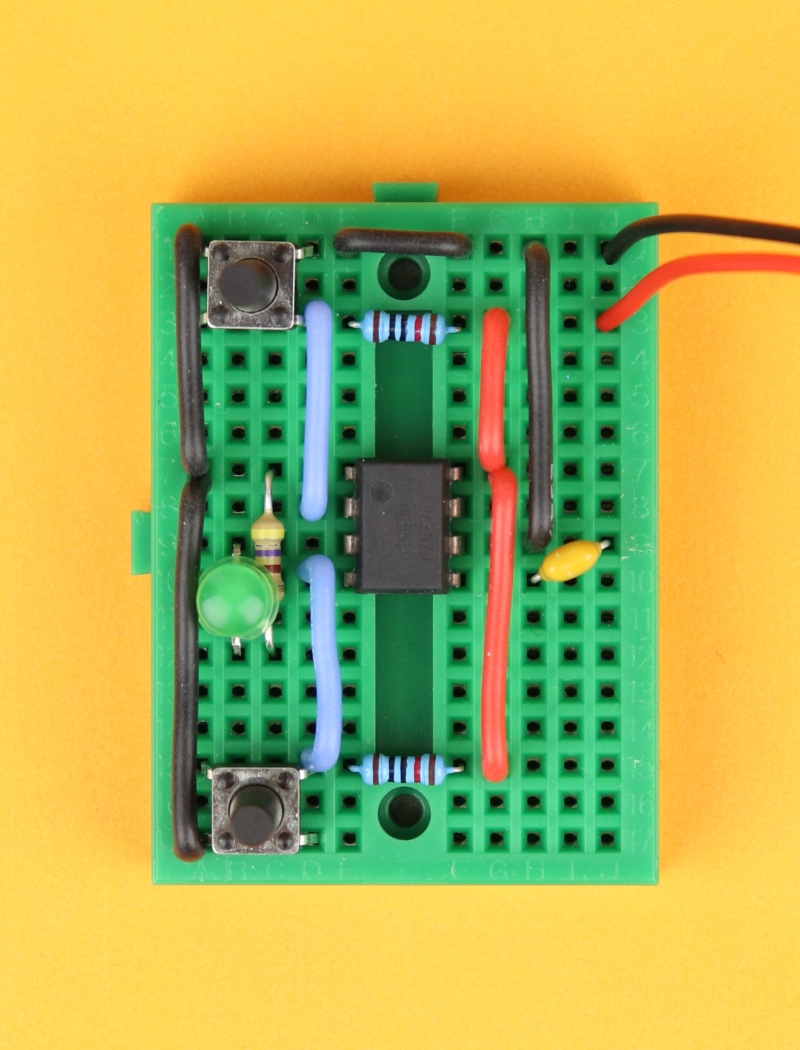
Here is the complete NE555 oscillator in all its glory. It's a bit difficult to capture the flashing LED in a photo, so be sure to check out the YouTube video as well if you want to see the oscillator in action :)
You can also insert a potentiometer instead of the two resistors R1 and R2, and the circuit then looks like this:
By turning the potentiometer you can adjust R1 and R2, and create different on and off times. In fact, this drive mode generates some sort of PWM because by turning the potentiometer you do not actually change the blinking frequency. Rather, you change the percentage that the LED is on.
If you want to use this as a realistic PWM to dim an LED (or to control a small motor), the capacitor C1 has to be chosen much lower in value so that the PWM frequency is high. If you choose R1 to be a 10kΩ potentiometer then C1=100nF would give you a PWM frequency of around 1kHz.
NE555 as a timer (“monostable” mode)
Say you want to turn on an LED for 5 seconds, and then turn it off again automatically. This is exactly when you can use the NE555 as a timer! This mode is also called “monostable” because here the LED is always off (the stable state) unless you press a button and the LED gets turned on for a fixed amount of time.
Here is how the schematic looks like:
Let's understand how it works!
- When nothing is going on and the circuit is powered on for the first time, the LED is off and the capacitor is discharged through the discharge pin because it is tied to ground.
- When you press the pushbutton S1, however, the trigger pin is grounded and sets the output of the NE555 to high. Also, it disables the discharge pin so that the capacitor C1 can now be charged over the resistor R1.
- The voltage on the capacitor slowly increases, and as soon as it reaches ⅔VDD the threshold pin resets the NE555 output to 0, and connects the discharge pin to ground, which immediately discharges the capacitor C1 (because there is no discharge resistor, this happens instantaneously without any delay).
- The capacitor C1 is now fully discharged, the output of the NE555 is turned off, and everything can begin all over again as soon as anybody presses the button S1.
We see: the LED is on only for a specified amount of time, and this time is determined by the capacitor C1 and the resistor R1 through which the capacitor is charged. This is the formula:
In our example we have R1 = 100kΩ and C1 = 22μF, so we have to insert 100 and 22 in the above formula. This gives us a time of t = 2420 milliseconds or around 2.4 seconds. If you want to increase the time, you can just insert larger resistors or larger capacitors, and if you need a smaller time then insert a smaller resistor or a smaller capacitor :)
Okay, now that that makes some sense to us let's go ahead and build it on a breadboard! Here are the necessary electronic components:
Again, you can find a detailed list of these components in the resources box :) Let's build the circuit!
-
-
Step 1
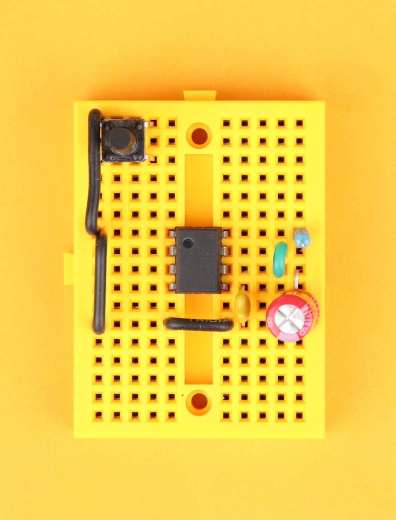
Place the 170-pin breadboard in front of you with row 1 facing up. Insert the NE555 in row 7 with its notch facing to the top left.
-
-
Step 2
Insert the 100kΩ resistor between pins 7 and 8 of the NE555.
-

-
Step 3
Connect pins 7 and 6 of the NE555 with a short piece of wire.
-
-
Step 4
Insert the 22μF capacitor between pin 6 and row 12, and make sure the negative terminal of the capacitor is connected to row 12. The negative terminal of electrolytic capacitors is usually highlighted with a big minus sign. Then, insert the 10nF capacitor between pin 5 and row 12, and this capacitor can be plugged in either way.
-
-
Step 5
Use black wire to create the ground rail. Connect row 12 on the right with row 12 on the left, then connect row 12 on the left with pin 1 of the NE555, and then connect pin 1 with row 1 of the breadboard.
-
-
Step 6
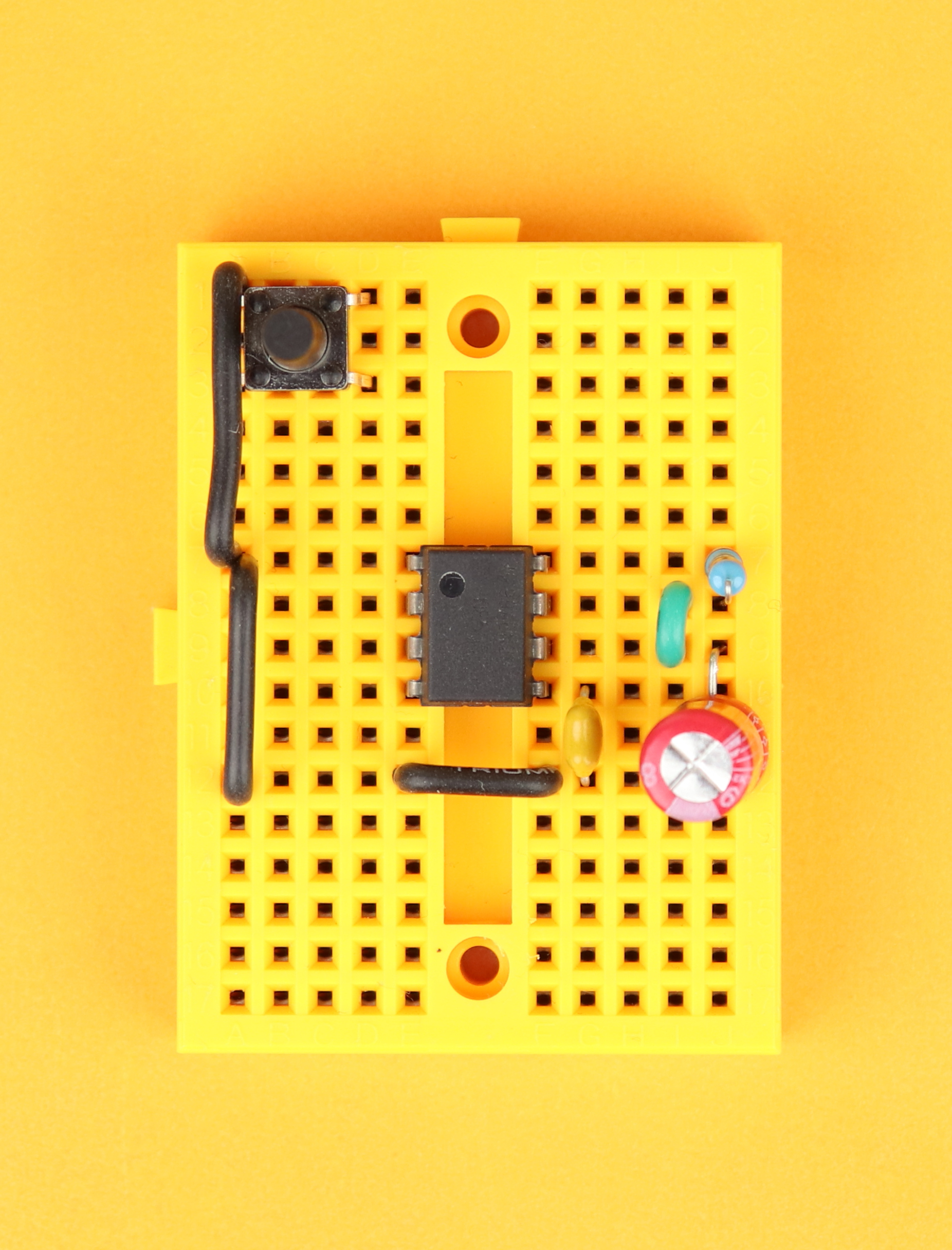
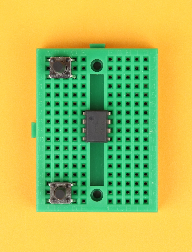
Place a pushbutton in row 1 of the breadboard. Take a close look at the picture and make sure you insert the pushbutton exactly like this, it is easy to accidentally rotate it by 90 degrees.
-

-
Step 7
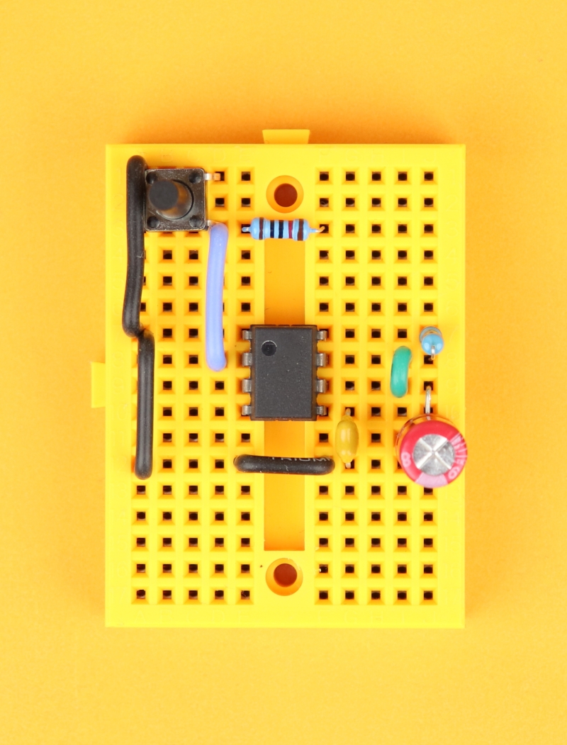
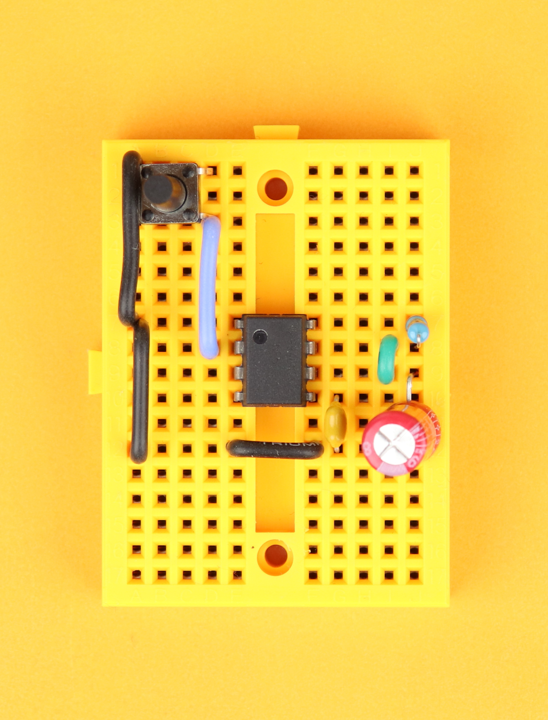
Connect the other side of the pushbutton (row 3 on the left) with pin 2 of the NE555.
-
-
Step 8
Insert the 10kΩ pull-up resistor in row 3.
-

-
Step 9
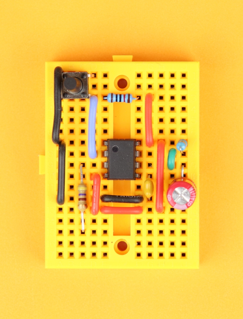
Create the VDD power rail where we will later connect +9V. First, connect the pull-up resistor with pin 8 of the NE555, continue down to row 13 on the right, then cross over to row 13 on the left, and finally connect to pin 4 of the NE555.
-
-
Step 10
Insert the 470Ω LED resistor between pin 3 of the NE555 and row 15.
-

-
Step 11
Insert the LED between row 15 and row 12. Make sure that the LED's anode (its longer wire) is connected to row 15 and that its cathode (the shorter wire) is connected to row 12.
-
-
Step 12
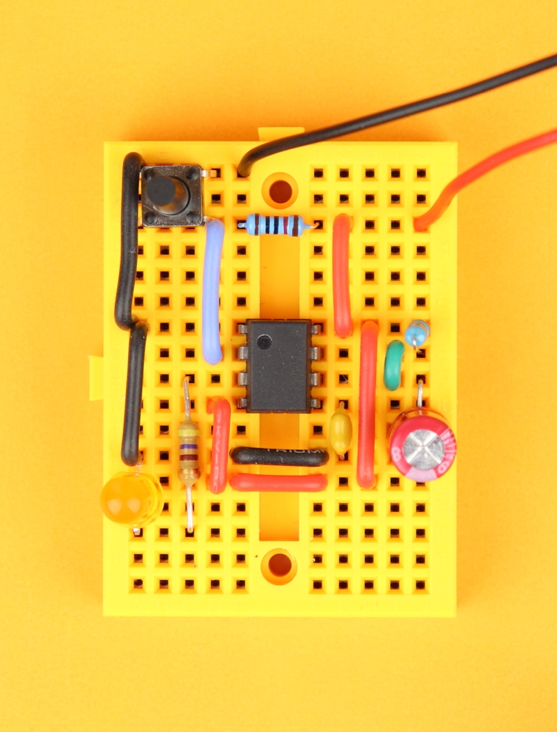
Connect the 9V battery clip. The positive terminal (red wire) can be plugged into row 3 on the right, and the negative terminal (black wire) goes into row 1 on the left.

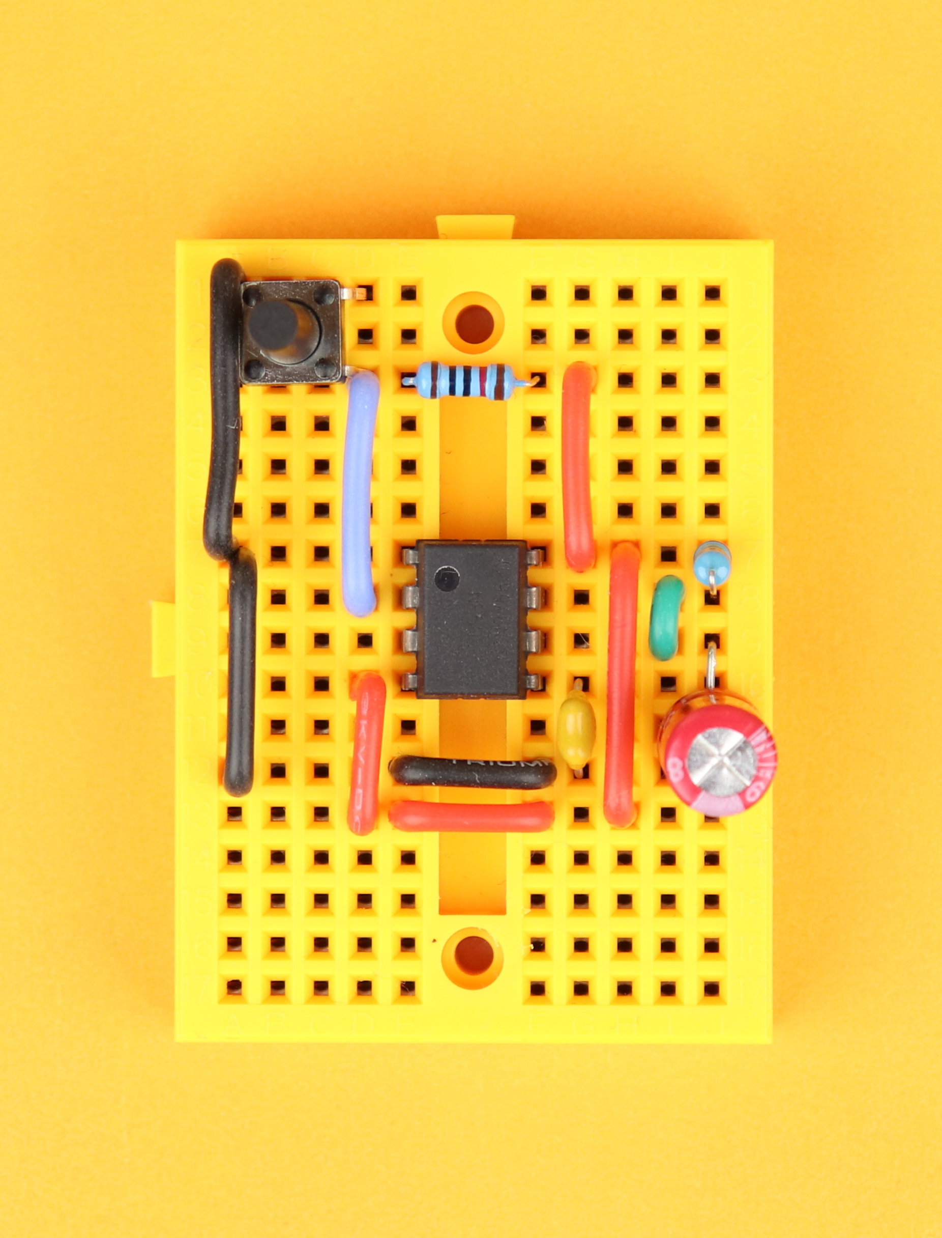


This is the finished NE555 timer, all set up and ready to go:
And, just as expected, when you push the button the LED turns on for around 2.4 seconds, before turning off again. If you want to see this in action you can check out the YouTube video below :)
NE555 as a flip flop (“bistable” mode)
At the very beginning we saw that the NE555 contains a flip flop, and we can forget about all the charging and discharging of capacitors and just use the flip flop on its own. This way, one pushbutton turns an LED on, and another pushbutton resets the LED back to zero. Both of these states are stable, which is why this mode is also called “bistable.” This is the schematic:
It only uses the two pins TRIGGER and /RESET, and it works like this:
- When you first connect the circuit to power, trigger and /reset are both high. This means that the output of the NE555 is low and the LED is off. When you press reset (S2), nothing happens, and the output stays low.
- But when you press set (S1), then trigger is pulled to ground, which sets the output of the NE555 to high and the LED turns on. If you press S1 again, nothing else happens, the LED stays on.
- But if you now press reset (S2), the NE555 resets to its default state and the LED turns off again.
This is pretty simple, and there are not even any formulas this time because this mode is bistable. Here is what you need if you want to build this circuit on a breadboard:
As before, you can find a detailed list of these components in the resources box. Let's go and build it!
-
-
Step 1
Place the 170-pin breadboard in front of you with row 1 facing up. Insert the NE555 in row 7 with its notch facing to the top left.
-
-
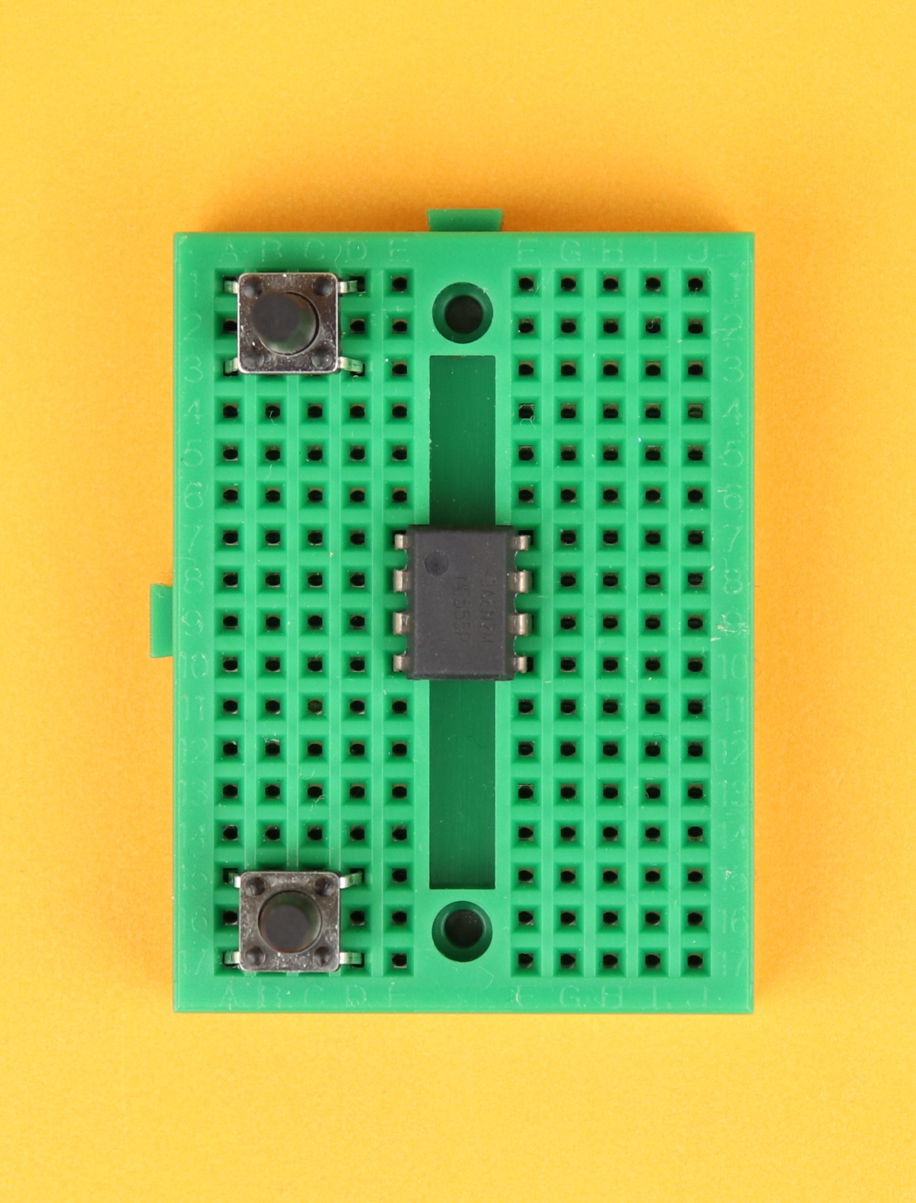
Step 2
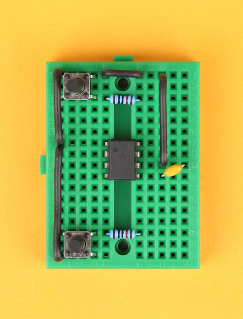
Insert the two pushbuttons in rows 1 and 15 on the left. Take a close look at the picture and make sure you insert the pushbuttons exactly like this, it is easy to accidentally rotate them by 90 degrees.
-
-
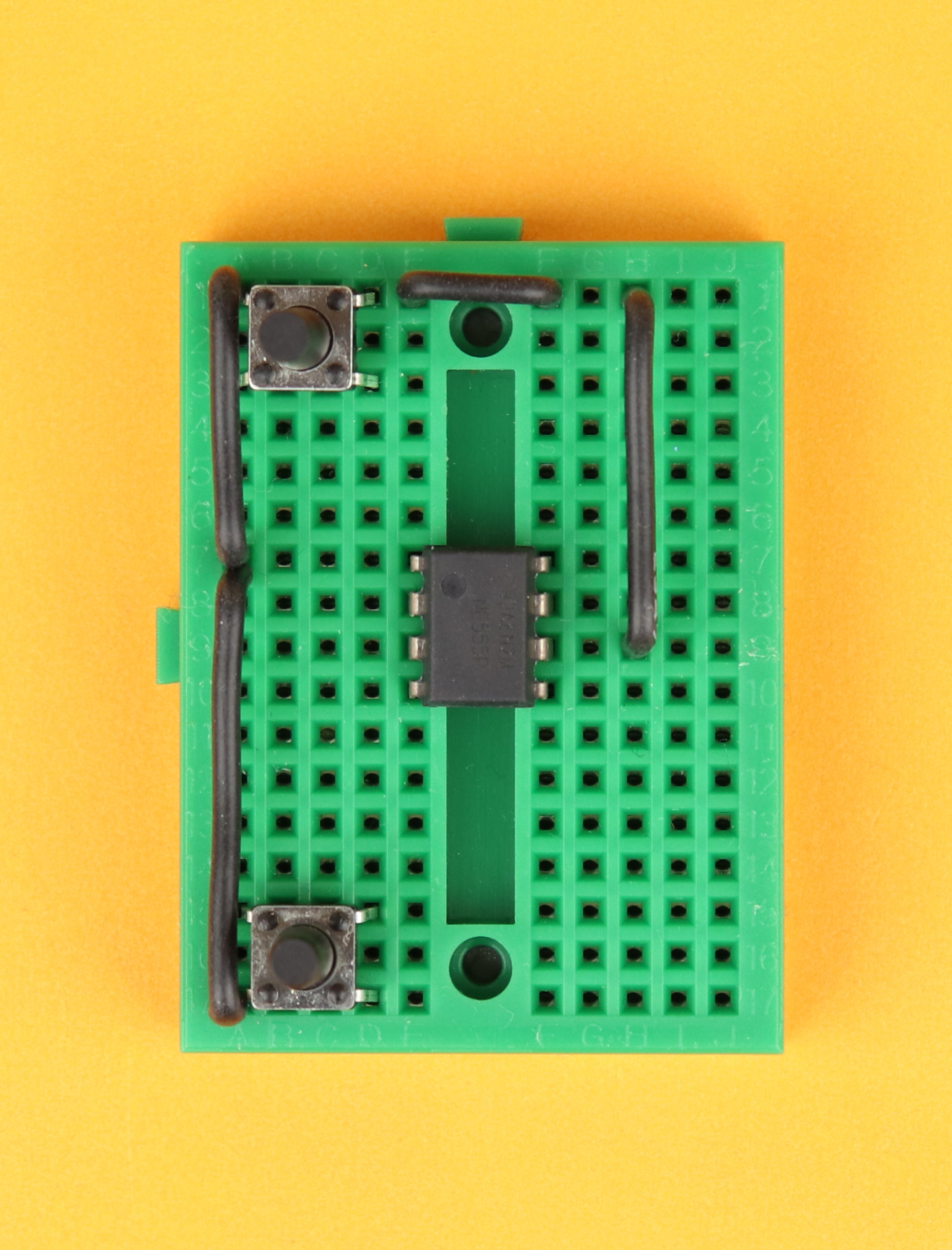
Step 3
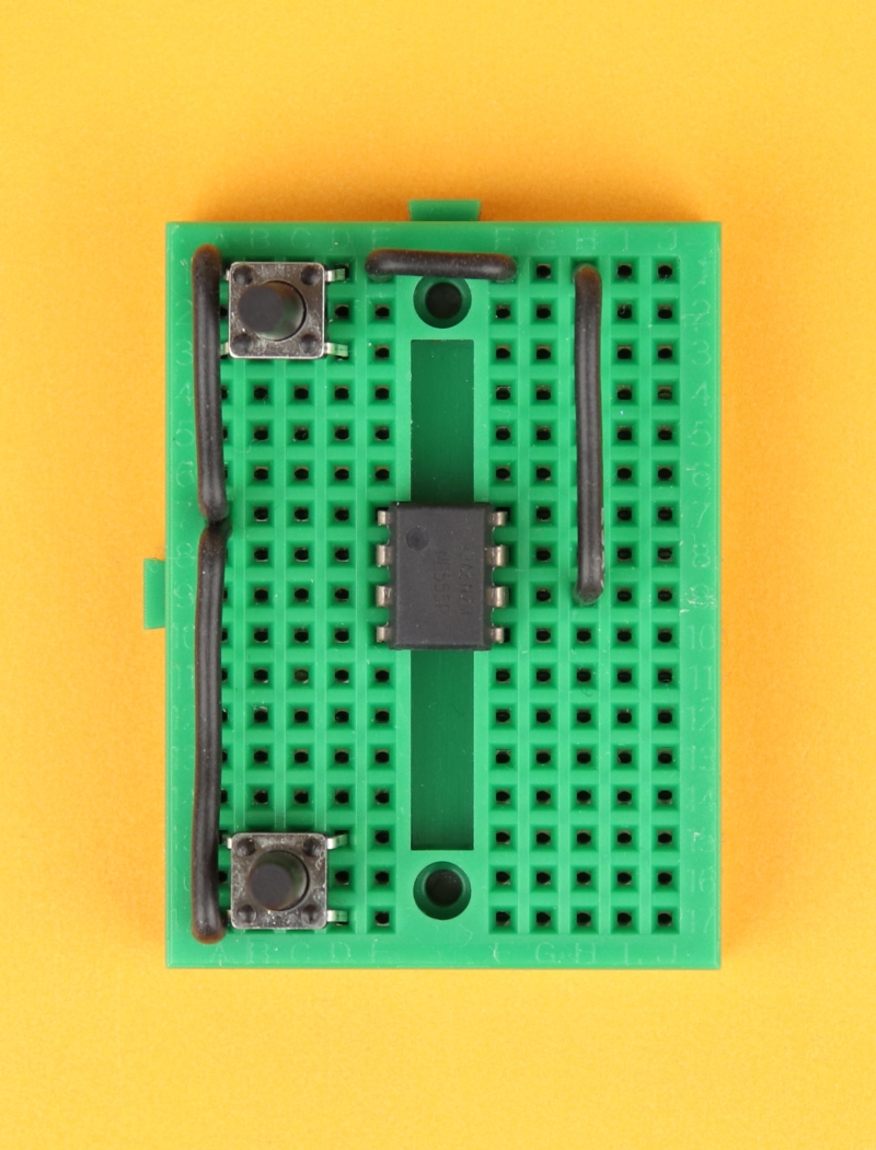
Create the ground rail using black wires. Connect row 17 on the left to pin 1 of the NE555, then continue up to row 1 on the left. Cross over to row 1 on the right, and then, finally, connect down to pin 6 of the NE555.
-
-
Step 4
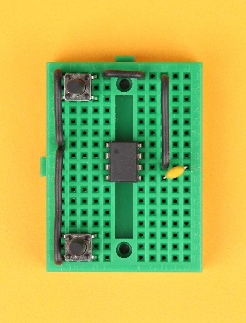
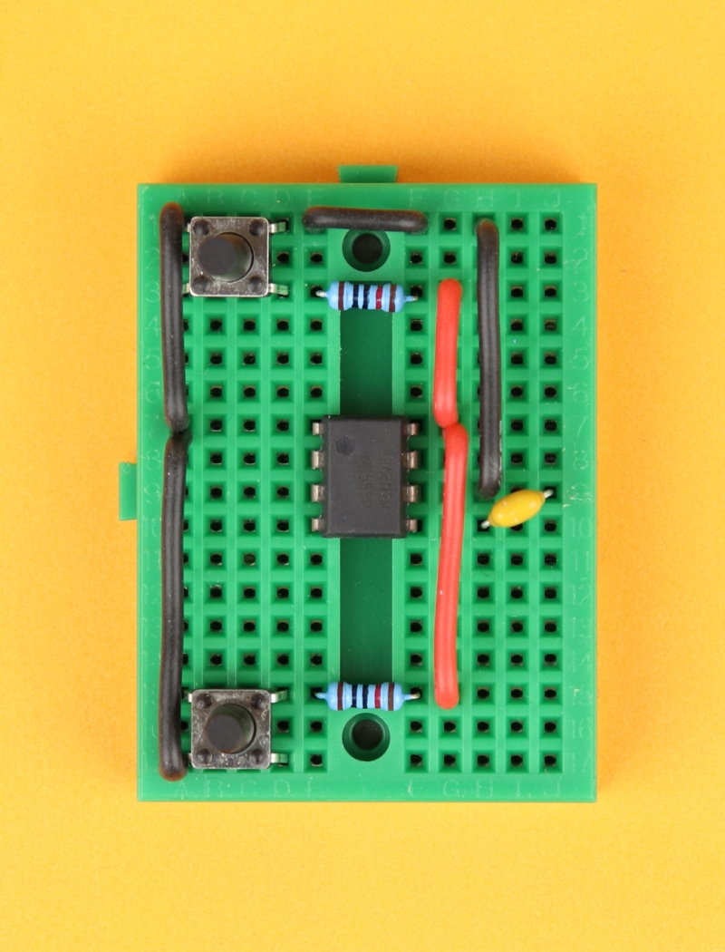
Insert the 10nF capacitor diagonally between pins 5 and 6 of the NE555. Its polarity does not matter, you can plug it in either way.
-
-
Step 5
Insert the two 10kΩ pull-up resistors in rows 3 and 15.
-
-
Step 6
Insert the VDD power rail that will later be connected to +9V. First, connect row 3 on the right to pin 8 of the NE555, and then connect down to row 15.
-
-
Step 7
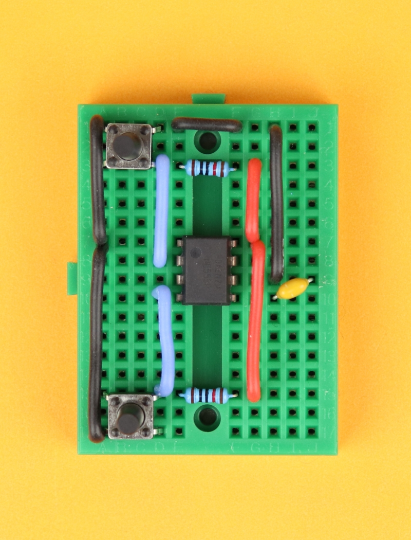
Connect the pushbuttons to the NE555. Row 3 on the left is connected to pin 2 of the NE555, and row 15 on the left is connected to pin 4 of the NE555.
-
-
Step 8
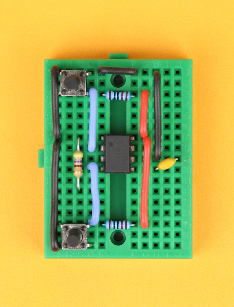
Insert the 470Ω LED resistor between pin 1 of the NE555 and row 12 on the left.
-

-
Step 9
Insert the LED between row 12 on the left and pin 3 of the NE555. Make sure that the LED's cathode (the shorter of the two terminals) is connected to row 12, and its anode (the longer of the two terminals) is connected to pin 3 of the NE555.
-
-
Step 10
Connect the battery clip. The positive +9V terminal plugs into row 3 on the right, and the negative terminal plugs into row 1 on the right.


Here you can see the final circuit, after I already pressed the set button:
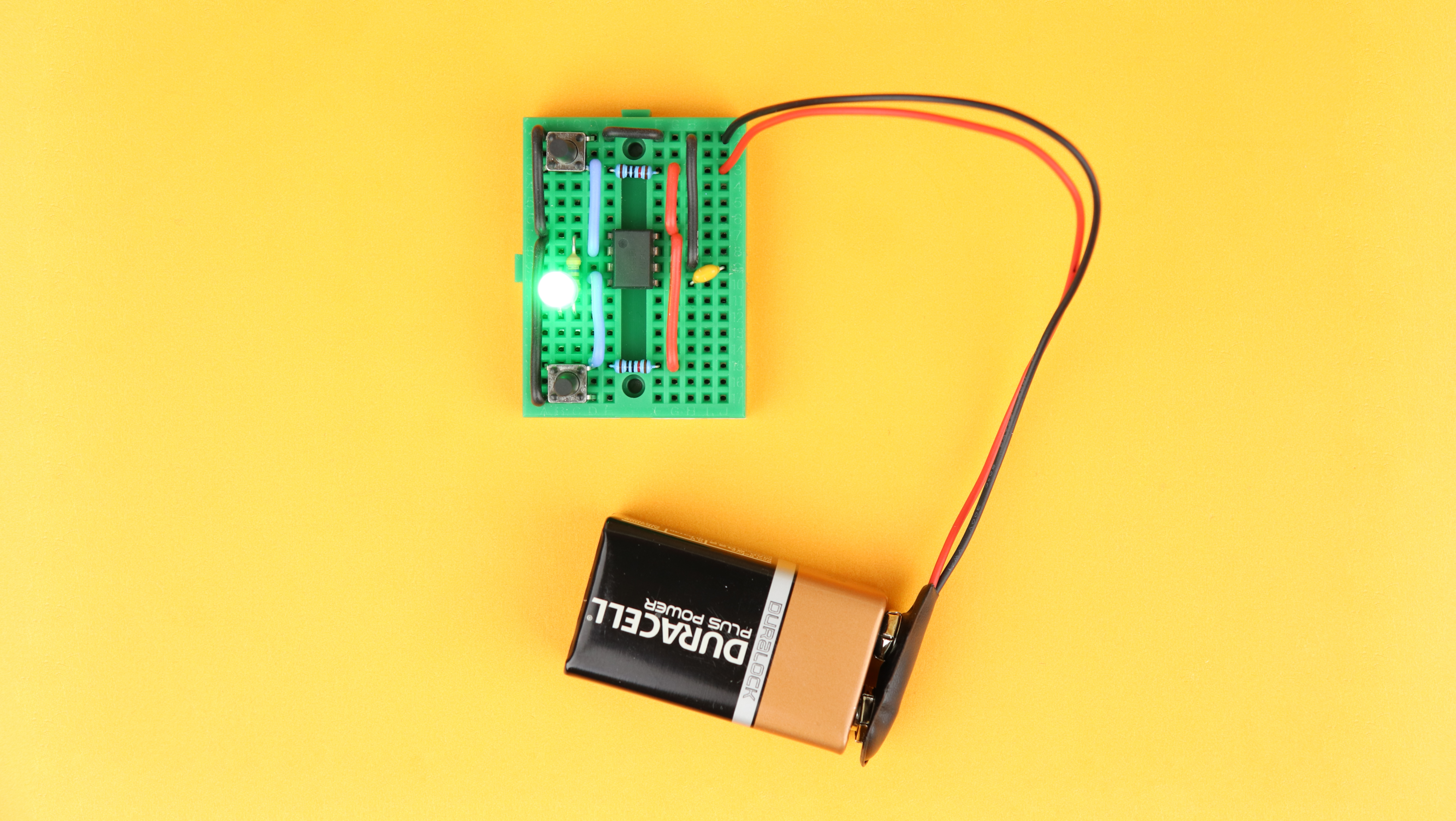
I really like this circuit, it is very simple but extremely useful in many situations :)
YouTube video
I covered this entire tutorial in a dedicated YouTube video:
Final thoughts

Here we are, you made it :) I hope I could show you that the NE555 is a very useful little integrated circuit, and I know that I will use it in a few upcoming projects. It's just a useful tool to have as a resource!
I also think that this tutorial shows that microcontrollers are not always necessary to do everything. Sometimes all you need is the good old NE555, and it has the additional advantage that you don't need a computer or any software to get it up and running.
Thank you for reading this article, and I hope you found it useful. If you have any questions, please get in touch on social media and I will do my best to get back to you. Have a great day!