LEDs 101 - what do you need to know?
March 29, 2019 • tutorial • last edited: May 22, 2019
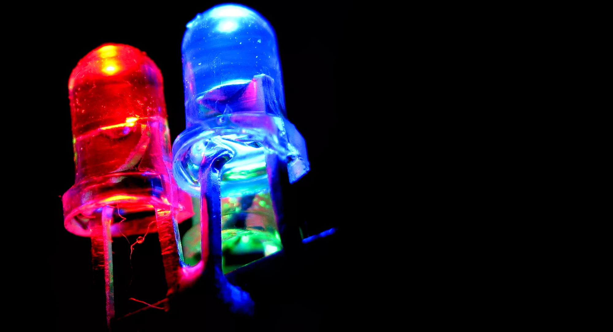
LEDs, or Light Emitting Diodes, are everywhere. Your smartphone? Check. Your microwave? Check. Your electric toothbrush? Check. In this article I want to present the basic ideas of how LEDs work and how you can use them in simple projects without having to rely on expensive after market solutions (such as wired LEDs with battery drivers that are expensive and often of questionable quality). Here we go!
ToDo
Add brightness discussion.
Basic parameters that describe an LED
There are a few parameters and technical terms that you should keep in mind when looking at LEDs. They have the following names and meanings:
- Current: Usually around 20mA, this is how much current your LED needs to glow. There are also so-called low current LEDs out there that require less current, typically around 2-5mA. The exact value will be listed in your LED's datasheet.
- Voltage: Depending on the color of the LED, the voltage that drops across them is slightly different. You can calculate it using Planck's constant and the exact wavelength of your LED, but typically the voltage is around 2V - 2.5V. It is a bit higher for blue LEDs (they have a shorter wavelength and therefore one blue photon requires more energy) and a bit lower for red and infrared LEDs. Again, the exact value will be listed in your LED's datasheet.
- Clear or diffused: This is pretty self-explanatory, but it is important to keep in mind. Some LEDs come with a diffused body, that is, the light will spread more isotropically, whereas others come with a clear body that will direct the light in a narrow cone.
- Beam angle: In case of a clear LED, light exits the LED body in a cone shape and there is usually an opening angle specified somewhere in the datasheet. A typical beam angle is between 30 - 60 degrees, but you can also look for more focused LEDs that have angles below 10 degrees.
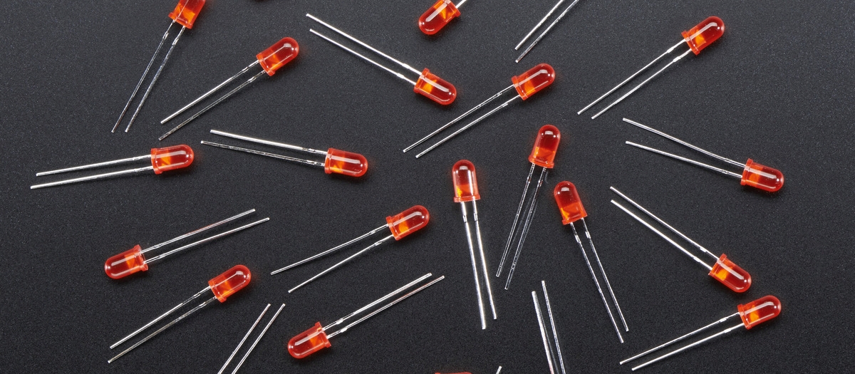
- LEDs come with a different diameter. Typical LEDs have 3mm, 5mm, 8mm, or 10mm diameter. There are other sizes and shapes as well, but they are less common. The larger the LED is, the more current it typically needs to glow. The voltage will be the same (for differently sized LEDs of the same color), provided there is only one LED chip in the body. If the LED consists of several chips in series, the voltages will add up.
- RGB: Yes, there are also RGB LEDs. These LEDs are special types that actually contain a red, green, and blue LED combined in one housing. Treat each one of these LEDs as a separate LED :)
- Blinking: Some LEDs have a blinking-circuit built-in. This can be useful but it can also be pretty annoying if you don't pay attention and actually needed a static LED instead of a blinky one. The datasheet is your friend!
- Pre-wired: Especially on online stores such as Amazon or Ebay you can often find "LEDs for 5V" or "LEDs for 12V." What does that mean? These LEDs come with a resistor that is calculated to work well with the specified voltage. These LEDs then do not need a current limiting resistor (see more below) and can be directly connected to the specified voltage.
Why are they called diodes?
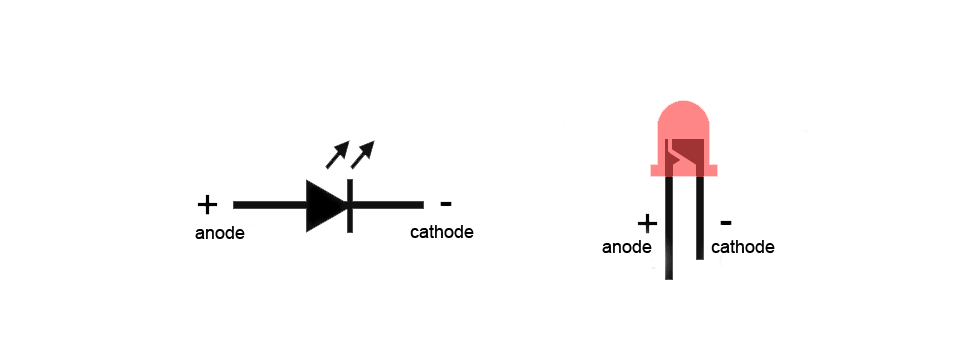
LED stands for light emitting diode, and diodes are devices that have a polarity. The positive terminal is called the anode, and the negative terminal is called the cathode. The short leg is the cathode, and the long leg is the anode. But don't worry: if you wire up an LED correctly and just get the polarity wrong, nothing happens. It just won't glow. In that case just switch the plus and minus cables and then everything will be alright. But don't forget the current limiting resistor that we will talk about next!
How do I calculate the LED resistor?
Usually, there are three parameters that you know when you are dealing with LEDs. The first one is the supply voltage that your circuit works with. That can be 5V, 9V, 12V, whatever you want. The second parameter is the LED current. If it is too high, it dies. Typical LED currents are in the range of 10-20mA (but the exact value is listed in the datasheet). We also know that LEDs have a typical voltage drop across the chip (this is the energy that is needed to emit light). This is roughly between 2V - 2.5V.
It is not very difficult to calculate the resistor that is needed to limit the LED current. You simply take the supply voltage and subtract the voltage that drops over the LED. Say your circuit works with 9V and your LED has a voltage drop of 2V. Then you need your resistor to kill the remaining 9V-2V=7V. You also know that the current should be, say, 20mA. Then we just use Ohm's law:
R = V / I = 7V / 0.02A = 350 Ohms
To be safe you can just go with 470 Ohms in that case. Another example? Sure! Say you have a 10mA LED at a 5V circuit (and the LED drops, again, 2V):
R = 3V / 0.01A = 300 Ohms
You get the idea. These parameters are not super critical. For standard LEDs I typically use 470 Ohms at 12V or 9V, and 220 Ohms at 5V.
Deluxe variant: constant current source!

Sometimes it is important to get the current exactly right. What, for example, if you have three LEDs in series? Then the voltage drop over all of these add up, sure. But manufacturing inaccuracies can lead to fluctuations of a few 0.1V when you have more than two or three LEDs in series. And what if one LED shorts out at some time? Then all other LEDs will surely die because the voltage drop is too high resulting in an increased current.
The solution is given by the voltage regulator IC LM317. Here you can see how to wire it up:
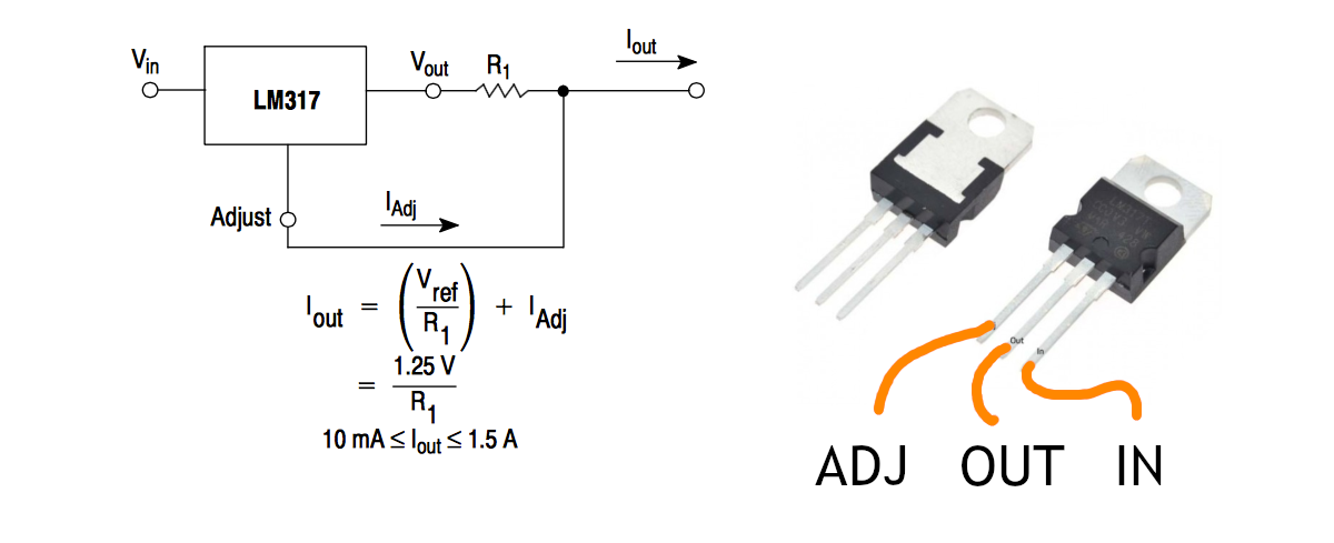
All you need to know now is the current you want to achieve. Say, it is 12mA. Then the resistor R1 in the above diagram has to have the value
R1 = 1.25V / 0.012A = 105 Ohms.
That was easy, wasn't it? The reason this is so simple lies in the fact that the LM317 is a smart device: an integrated circuit that regulates the current if it is wired up as indicated above. The voltage drop that was killed by the current limiting resistor in the previous example is now just dissipated as heat through the heat sink of the LM317.
A word of caution: This works well when you want to drive, say, four LEDs in series at a voltage of 12V. It does not work well if the voltage drop is too high because then the LM317 will have to dissipate too much heat.
Sometimes it is a good idea to combine these tools: put in a small current limiting resistor (to kill, say, 5V or so) and then do the fine-tuning with the LM317-circuit in series. Then you have the best out of two worlds: current regulation (in the word's true meaning) and not too much heat dissipated. Great!
Prewired LEDs
Here is a small video I made where I describe how to make your own pre-wired LEDs.
For prewired LEDs for 5V you will need to use a 220 Ohms resistor, and for 9V or 12V I recommend 470 Ohms.
The LED rainbow - have fun!
LEDs are everywhere, and I hope that with this article you feel more confident when it comes to choosing an LED for your next project. Let me know if this article was helpful or not, and what you want to read about next! Thanks for reading :)