Breadboard capacitive touch sensor tutorial
May 15, 2021 • tutorial
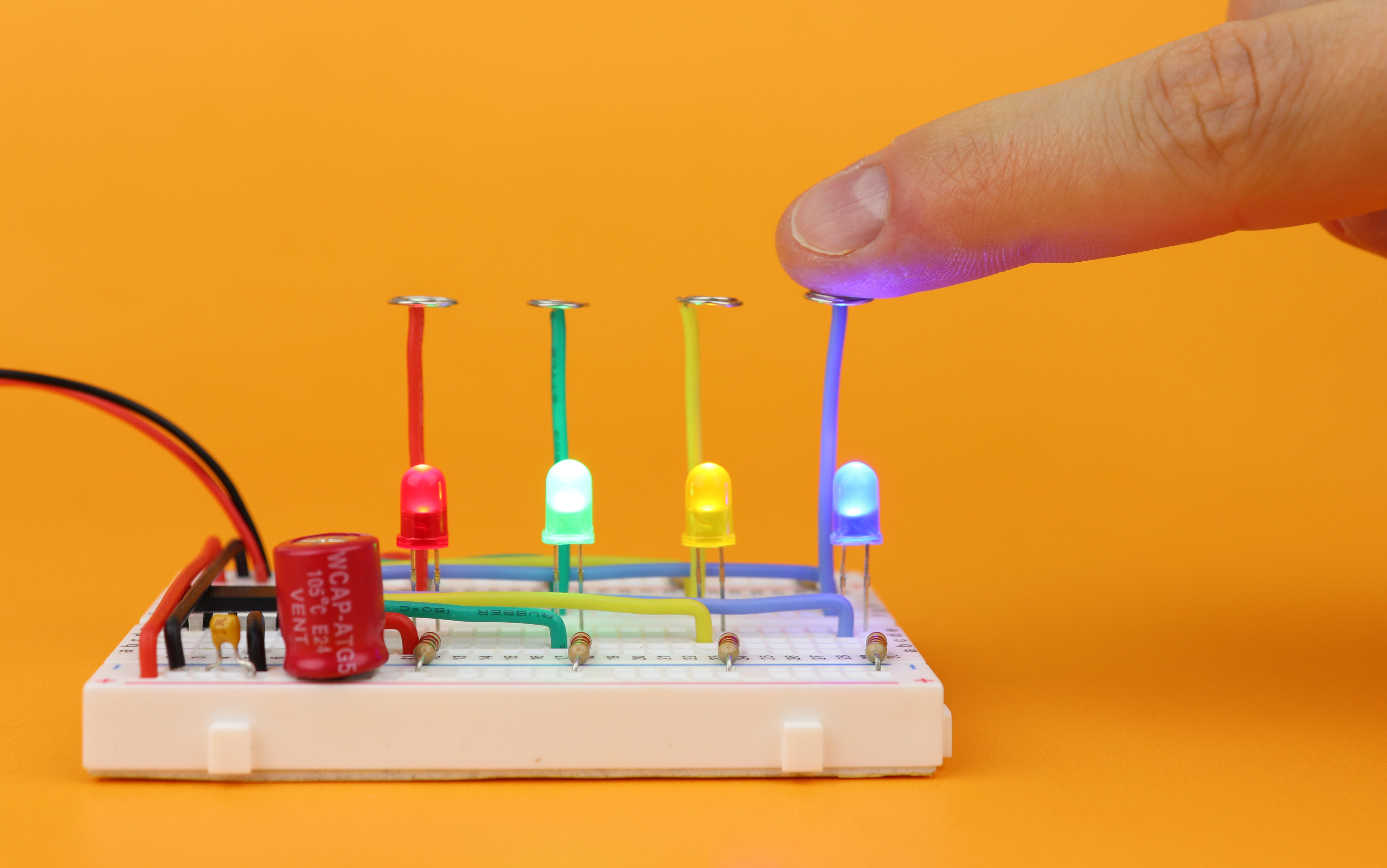
Capacitive touch sensors are everywhere, and today we will learn how to build one from scratch on a breadboard with a PIC microcontroller, a resistor, and a wire. And to keep things interesting, we will build a momentary switch, a toggle switch, a timer, and a 3-level dimmer. Let's go :)
In this article you can find all the information you need to build this touch sensor yourself; if you are more the visual type you can also check out my YouTube video.
What you need
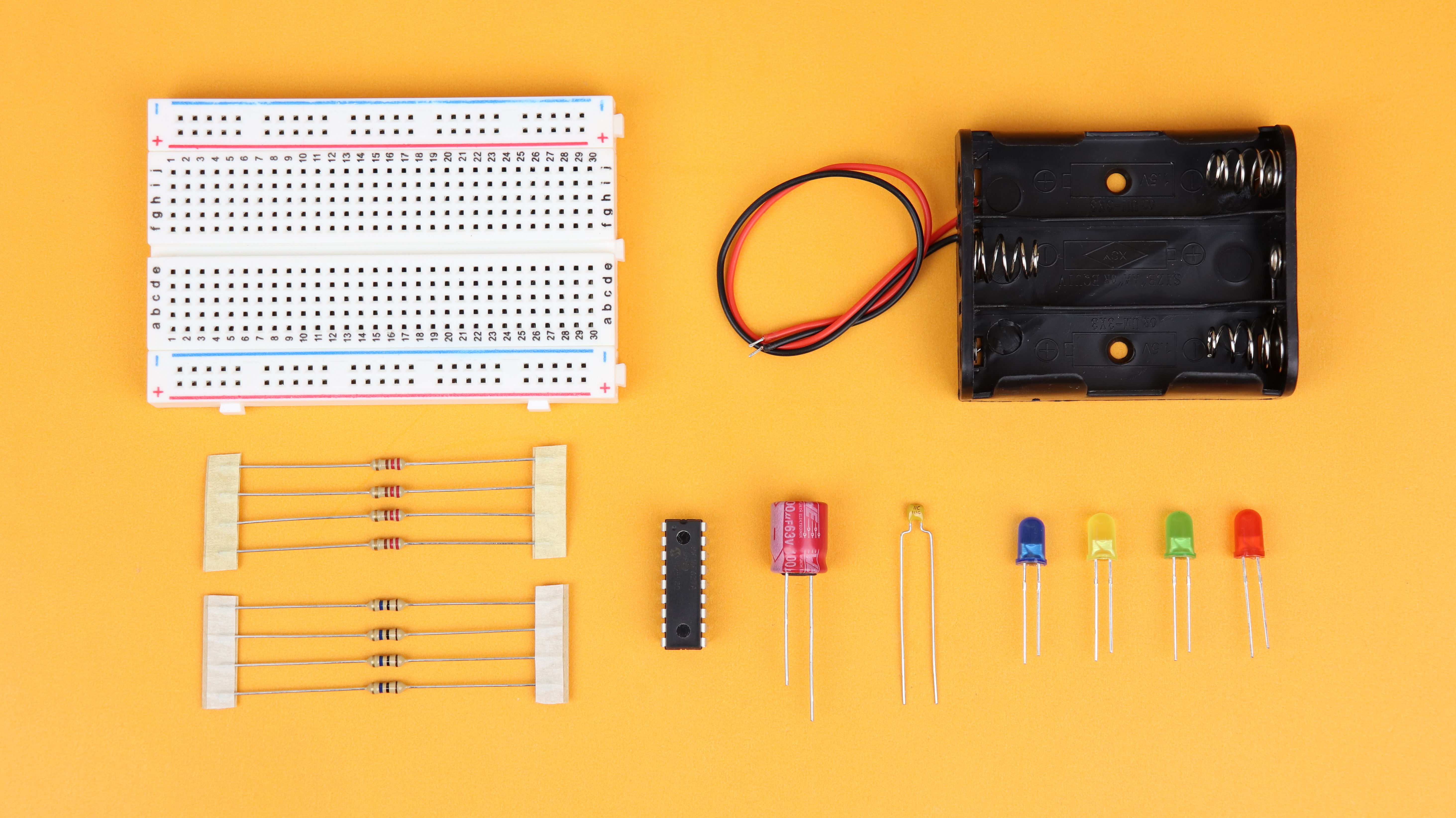
You can build this touch sensor with any microcontroller, and we will use the PIC16F627A. Other than that you only need some wire and a 10MΩ resistor, because the breadboard will play the role of a capacitor, more on that later. The LEDs are just there so that we can visualize that the touch sensor is actually working as intended. So you see: you don't need a whole lot of parts to build your own capacitive touch sensor on a breadboard.
And as always you can find a detailed list of all components in the components box in this article :) Because this project is a microcontroller project it's also a good idea to make sure you understand the microcontroller basics, and I recommend to look at these three beginner-friendly step by step articles:
- Your first microcontroller program
- How to flash a PIC microcontroller
- Make an LED blink: your first simple PIC microcontroller project!
And if you prefer an all-in-one tutorial then I invite you to check out my PIC introduction video on YouTube :)
Capacitive touch: main idea
So how does a capacitive touch sensor work? It's really quite simple, here is the main idea:
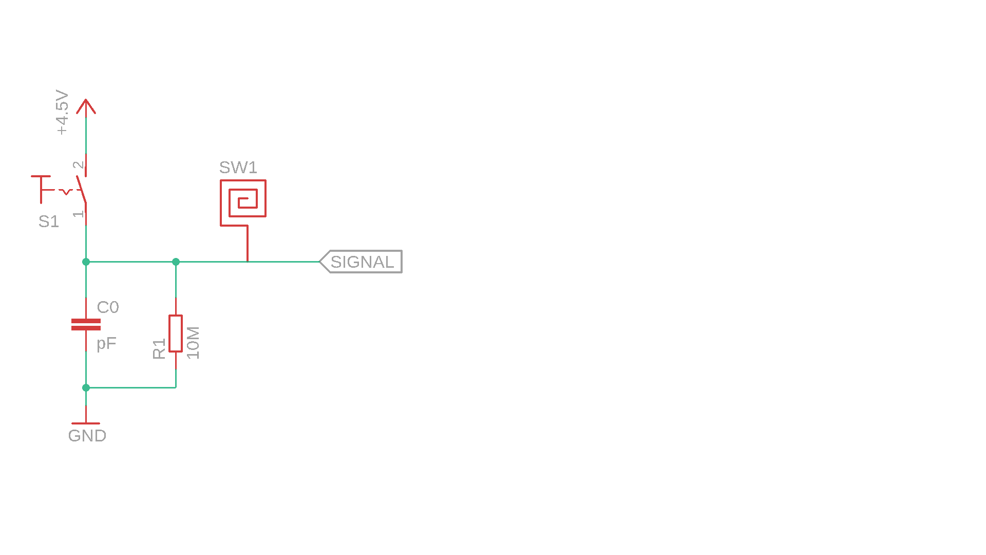
- SW1 is our symbol for the actual touch sensor, and we can make one out of simple wire.
- The main components are the the capacitor C0 and the resistor R1. Later on, the stray capacity of the plastic breadboard itself will work as our capacitor C0.
- The switch S1 will be replaced by a microcontroller later on, it's just here to visualize the main idea. It turns on for a fixed time to charge the capacitor, and then it turns off. You can think of this as a kind of probe signal:
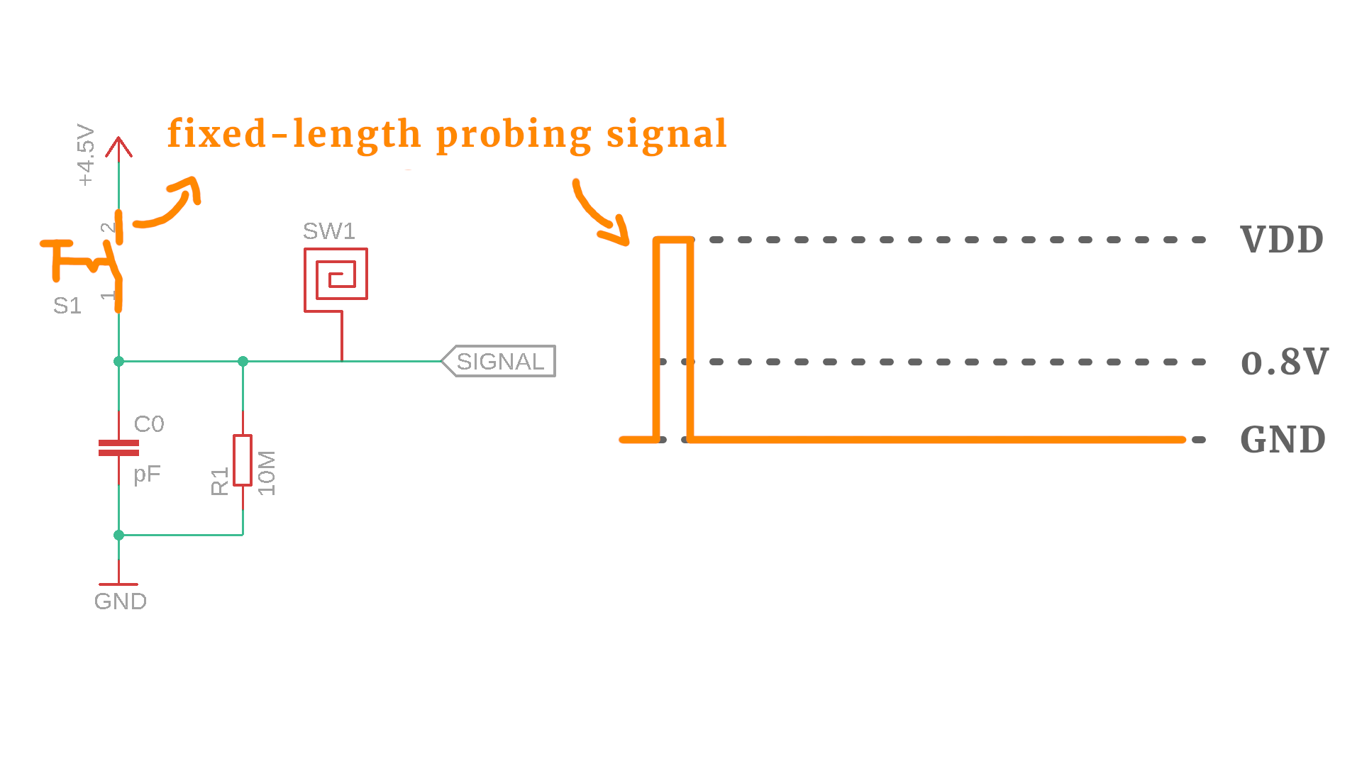
But what happens when the probe signal is switched on and off?
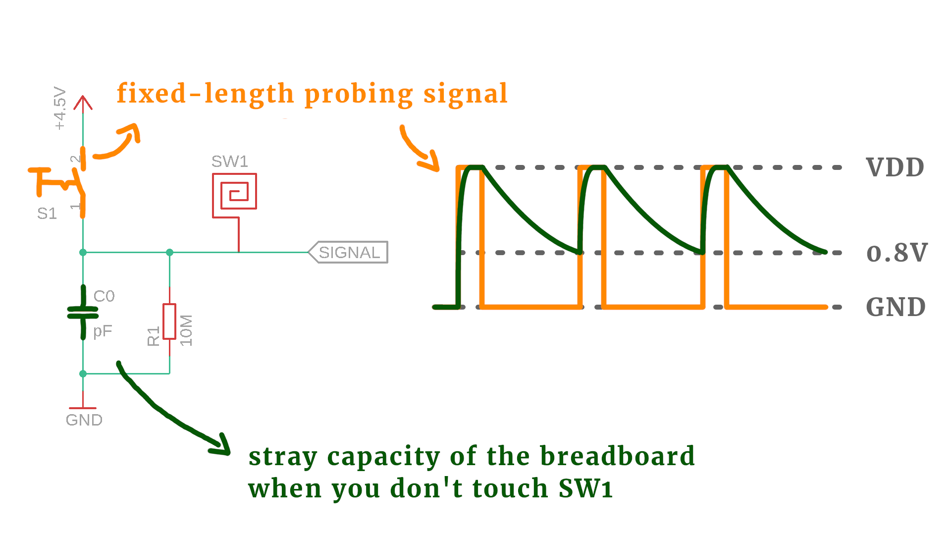
- When the switch is on, the capacitor C0 charges up rapidly, and when it is turned off again, the capacitor C0 discharges through the big resistor R1. How fast that discharge happens depends on the values of C0 and R1.
- And when the voltage at the capacitor has discharged below 0.8V, then the switch turns on again for a fixed time, and the whole process happens all over again. That voltage seems kind of random, and in principle it doesn't matter to what voltage the capacitor discharges, but 0.8V is the highest voltage that still qualifies as a TTL low level, more on that later.
- Anyway, using this method we can find an average time that it takes for the capacitor to discharge down to 0.8V.
OK, so now imagine you touch SW1. What happens then?
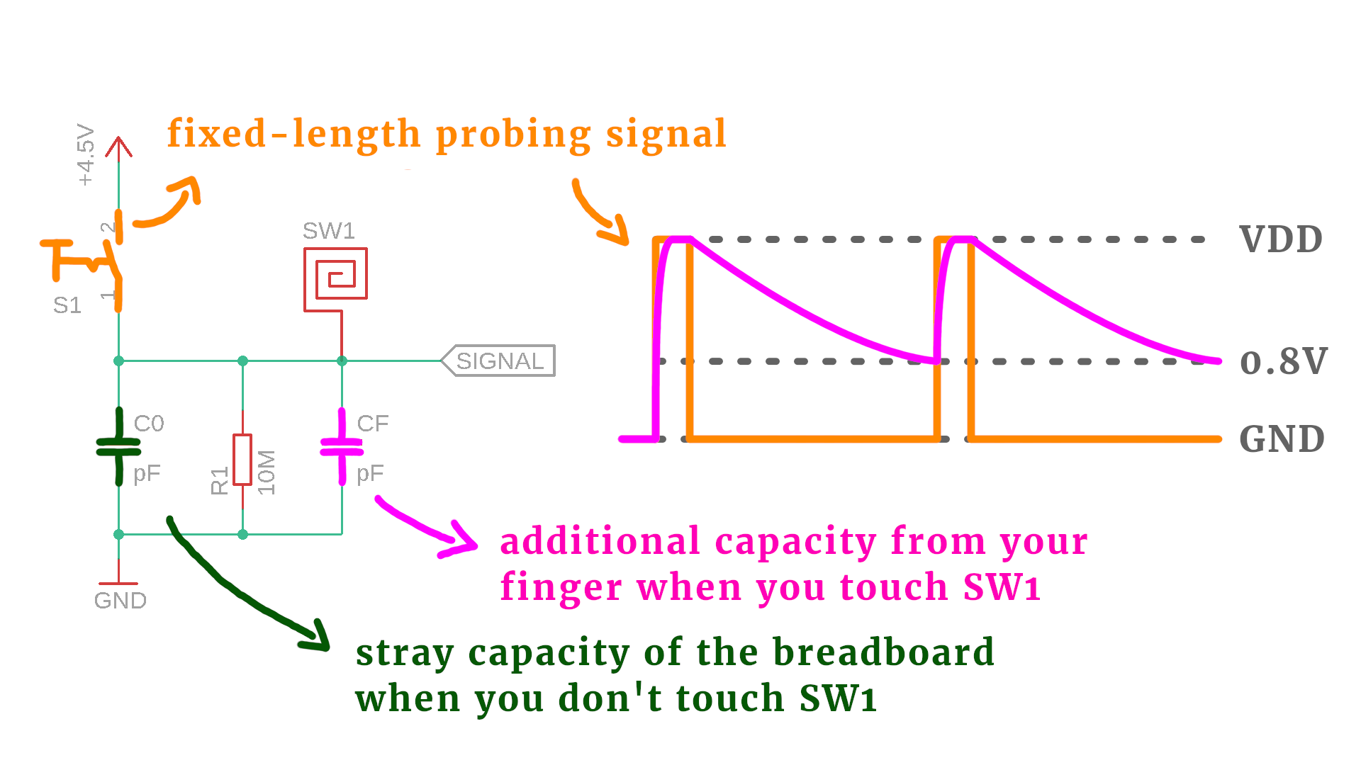
- Whenever you touch SW1, the capacity of your finger gets added in parallel to C0, and I call your finger's capacity CF :) This makes the discharge take longer, because now the total capacity is the sum of C0 and CF.
- So you see: the circuit knows that somebody is touching the touch sensor, whenever the discharge time suddenly gets longer! In other words: whenever the discharge time is larger than the average one by some threshold, we know that somebody is touching the sensor.
In this tutorial we don't have to use any capacitors for the touch switch in our circuit! We are building the circuit on a breadboard, and breadboards have stray capacities. What are those?
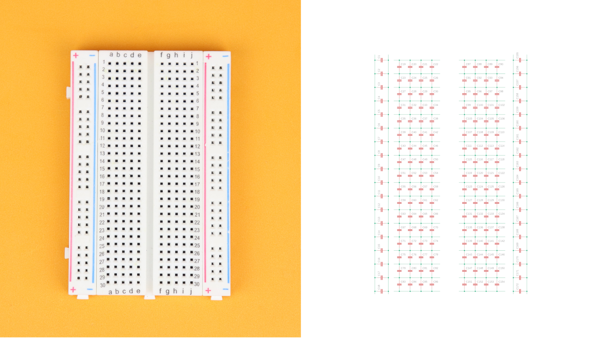
On the left you can see a breadboard, and on the right you see its equivalent circuit. The green lines are the lines of the conductors, as you would expect, but in between are a lot of capacitors. Basically, the plastic insulator between the conducting rails of the breadboard creates a very small capacitor. We call it stray capacity, and it is in the range of a few picofarads, that is a millionth of a millionth of a Farad, so quite small. But it's there, and we will use it!
In our tutorial we also won't use a switch S1 to turn our signal on and off, but we will use a microcontroller instead:
Microcontrollers have a clock speed, which will be 4MHz (four million cycles per second) in our case. For PIC microcontrollers this means that they can do one million instructions per second, or, one instruction per microsecond. So we have to ask ourselves: are they fast enough to measure these discharge time changes?
The answer is: yes! With the stray capacity C0 around a few picofarads, and the resistor at 10MΩ (a million ohms), the discharge time is in the microseconds range. So it works out perfectly! (To make it work we had to use the really large 10MΩ resistor. If you used a 220kΩ resistor instead, the discharge time would be much smaller and much harder to measure.)
Schematic
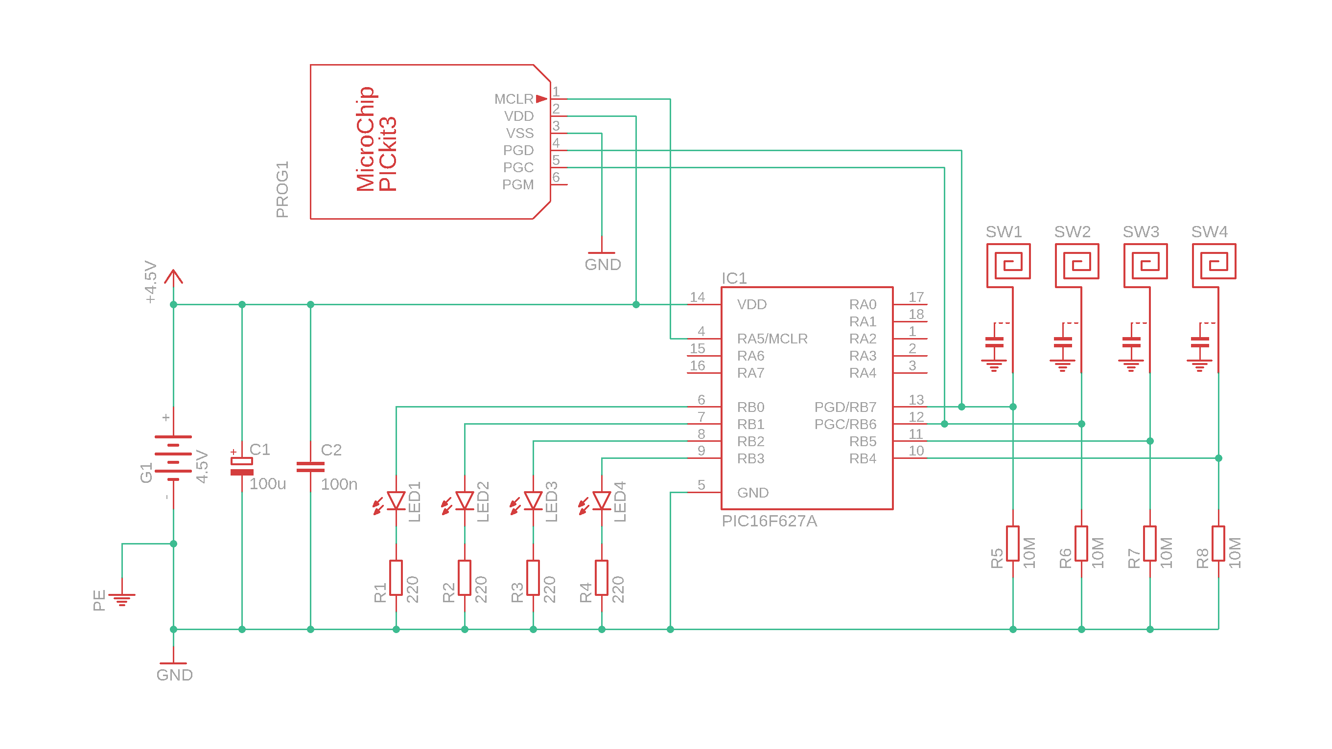
To keep things interesting I decided to build four touch switches all on one breadboard, and here is the breadboard touch switch schematic:
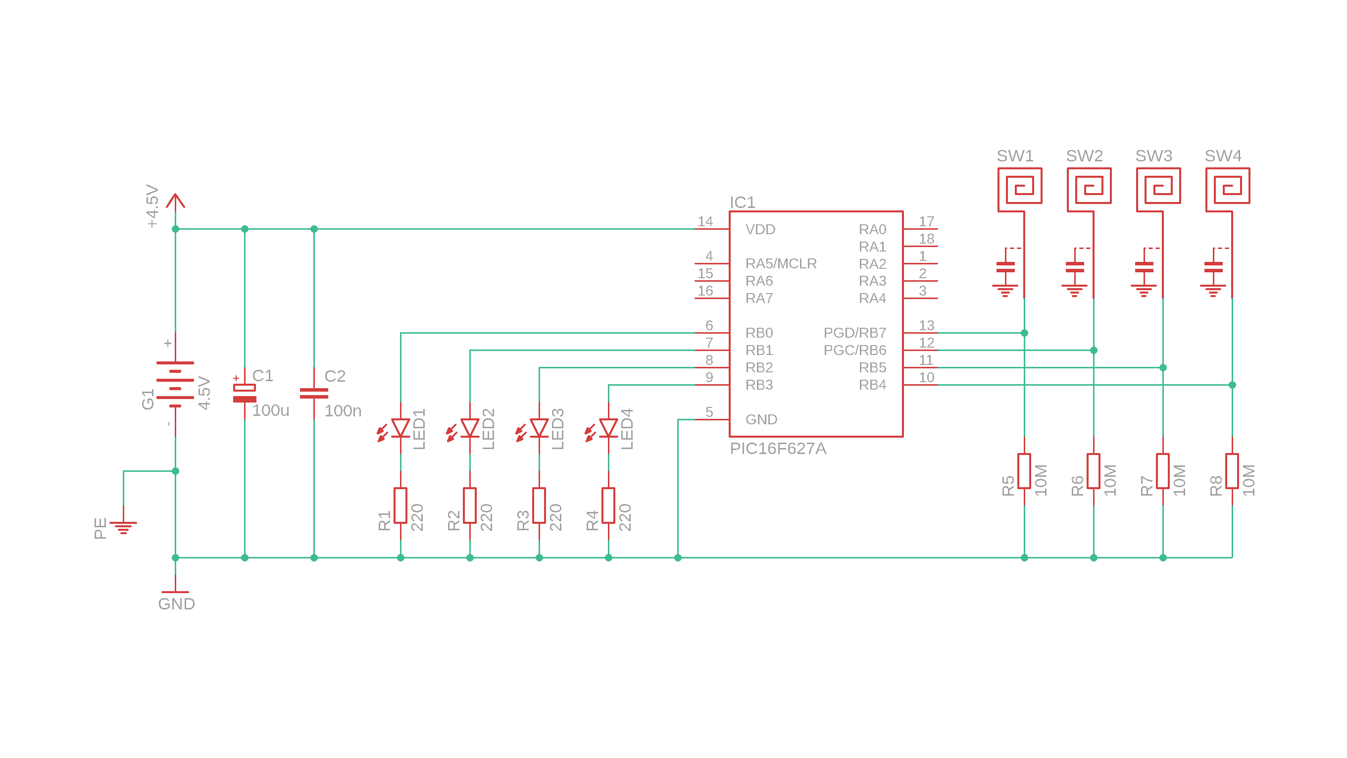
And, as always, let's go through the main components step by step:
- G1 is a battery pack with 3 AA batteries that provide 4.5V to run our circuit, C1 is a bulk capacitor, and C2 is a bypass capacitor. They have nothing to do with the capacitors that do the touch sensing, they are just built in to stabilize the circuit.
- IC1 is the PIC16F627A microcontroller, on which we will program our touch switch functionality. But the method we use here is very simple and works with any other PIC microcontroller as well :)
- SW1–SW4 are the touch contacts. They are basically just a piece of wire with one end wrapped into a circle so it is easier to touch and you don't poke yourself. The capacitor symbol next to the touch contacts is there to remind us of the stray capacitor of the breadboard.
- R5–R8 are the discharge resistors, and it is important that they have the large value of 10MΩ.
- And last, LED1–LED4 as well as R1–R4 are simple status LEDs that turn on whenever their touch switch is active.
- Okay, but what is that PE symbol at the bottom left? It stands for “protective earth” and for our purposes it is basically a proper ground connection to a huge chunk of metal. Sometimes this is necessary to make the circuit work reliably, and we will talk about it some more later :)
I hope this all makes sense. Now that we understand the hardware, let's talk about the software as well: we need to write a simple program that tells our controller what to do. So let's do that next :)
Writing the software
As always, I will use the freely available MPLAB X integrated development environment to write C code for the also freely available XC8 compiler. You can download the C source file (main.c) in the resources box, as well as the .hex file that we will later flash onto the controller.
I know, this part can always be a little bit intimidating, and if you're completely new to PIC microcontrollers then I invite you to check out the article on your first microcontroller program as well as the PIC introduction video on YouTube :) You got this!
But here is the lightning summary! First, open the MPLAB X IDE and click on File → New Project:

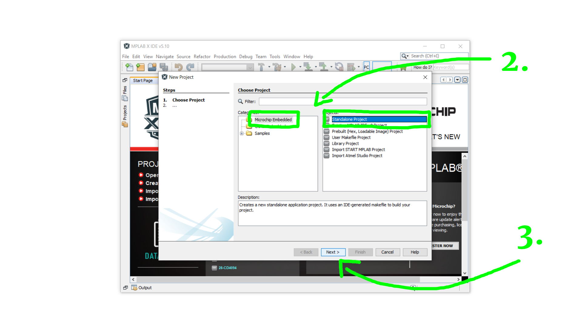
Select Microchip Embedded and Standalone Project and then click on Next:
Under device select the PIC16F627A and click on Next:

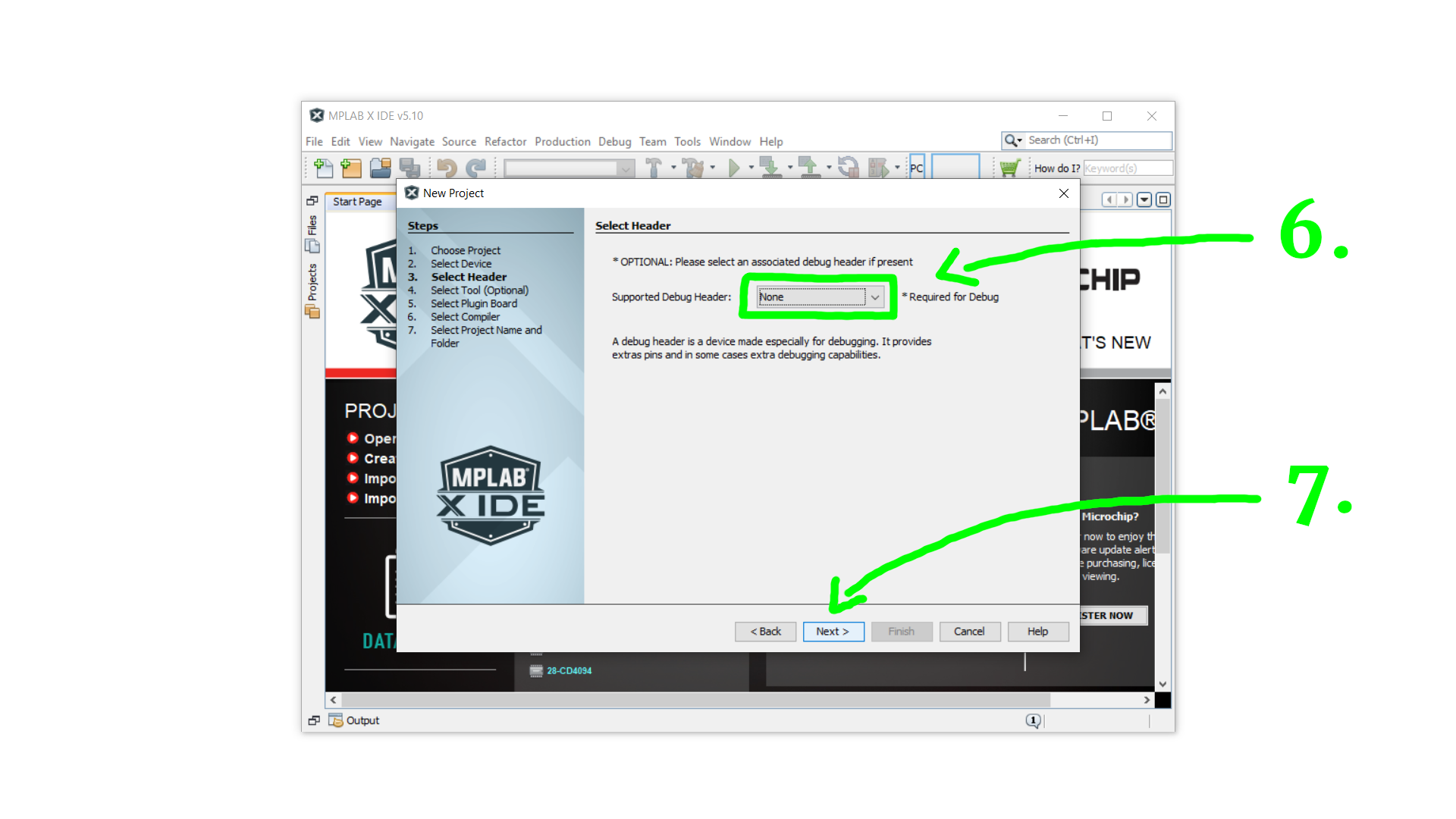
Since we don't need a debug header just select None and click on Next:
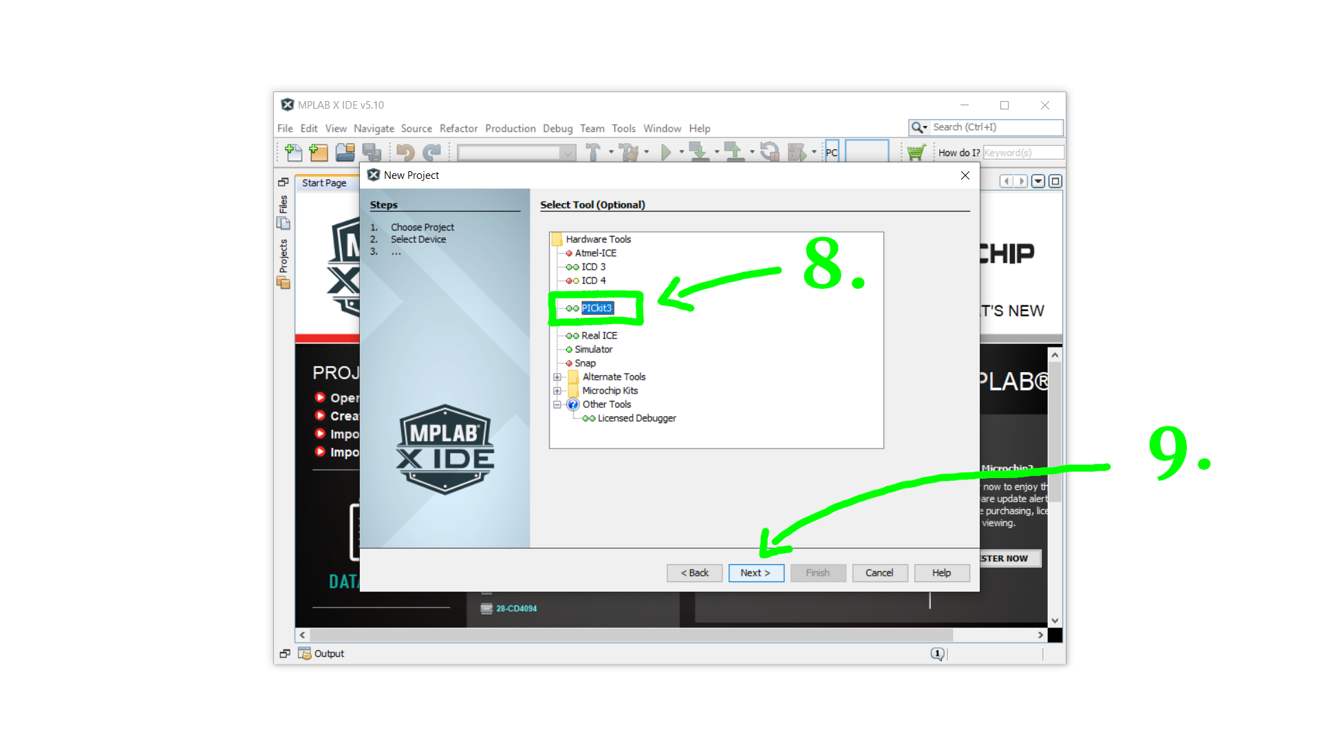
Select the PICkit3 as a tool and click on Next:
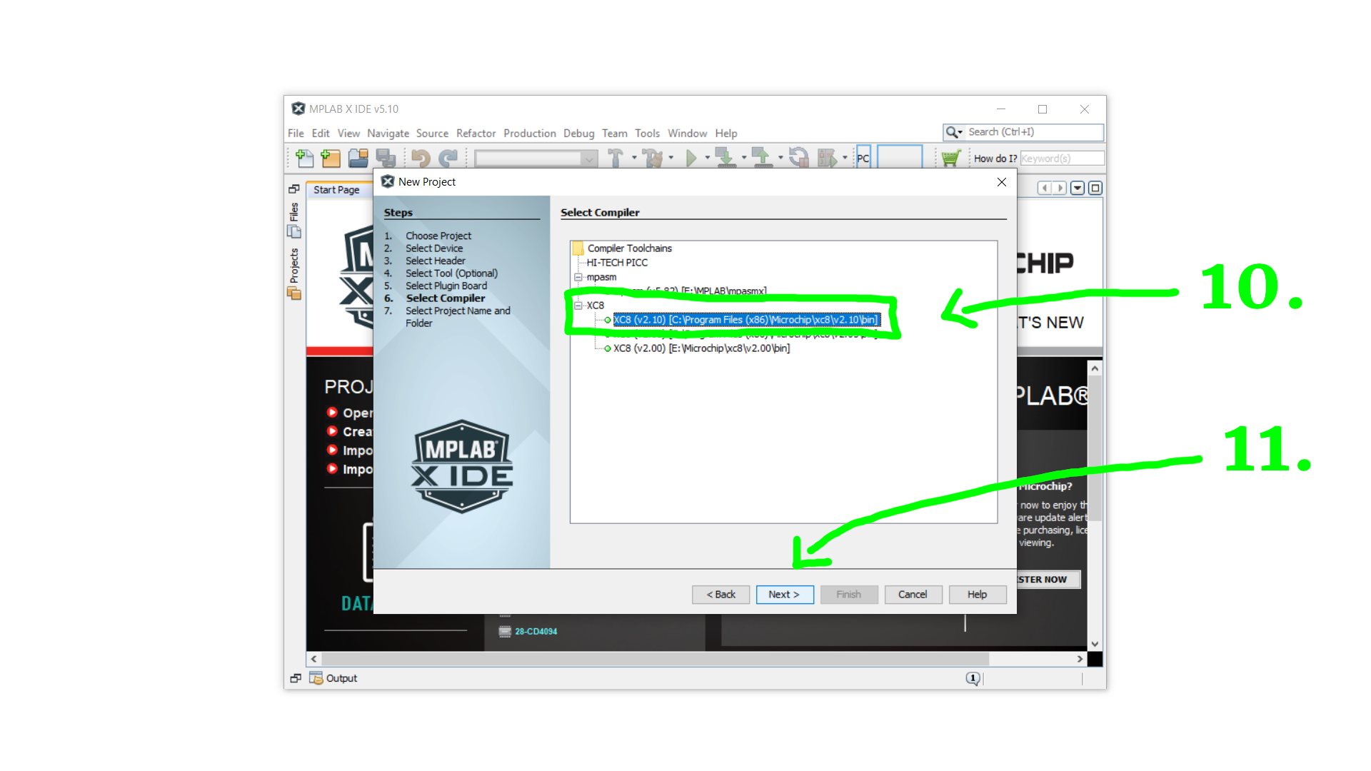
As a compiler you can select any XC8 compiler that shows up in this list. If none show up you need to install it first. Then click on Next:
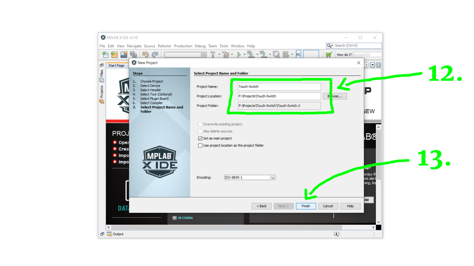
Then you can fill in the project name and select its location on your computer, and finally click on Finish.
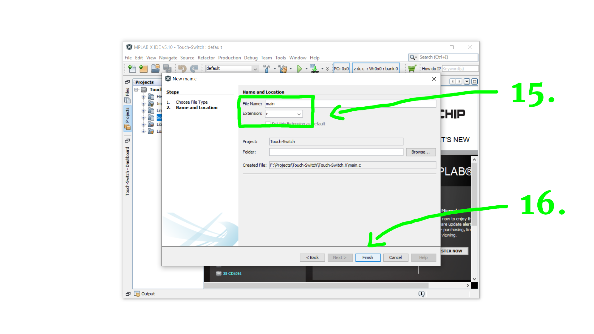
We now created our project. On the left side, inside the Projects tab, right click Source Files, click on New, and then on main.c to set up the source file.

Enter main as a file name and click on Finish:
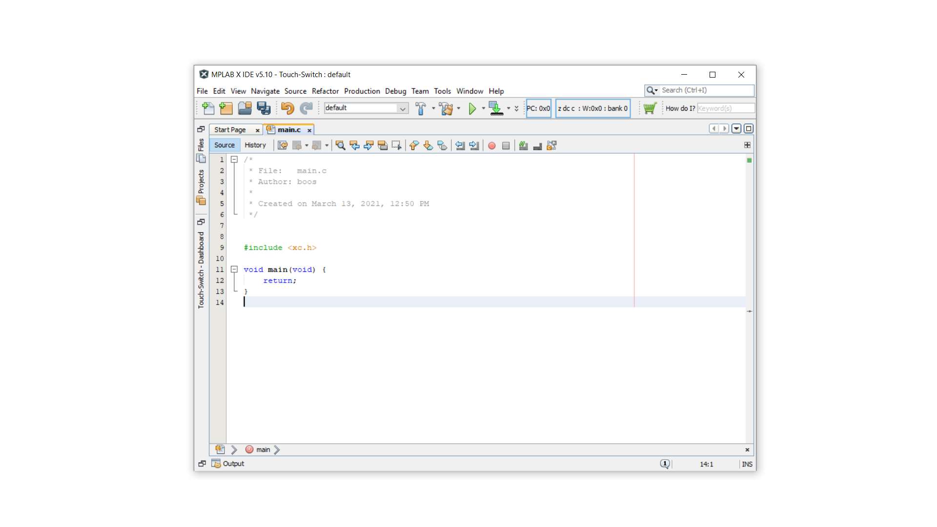
This is what you will see next:
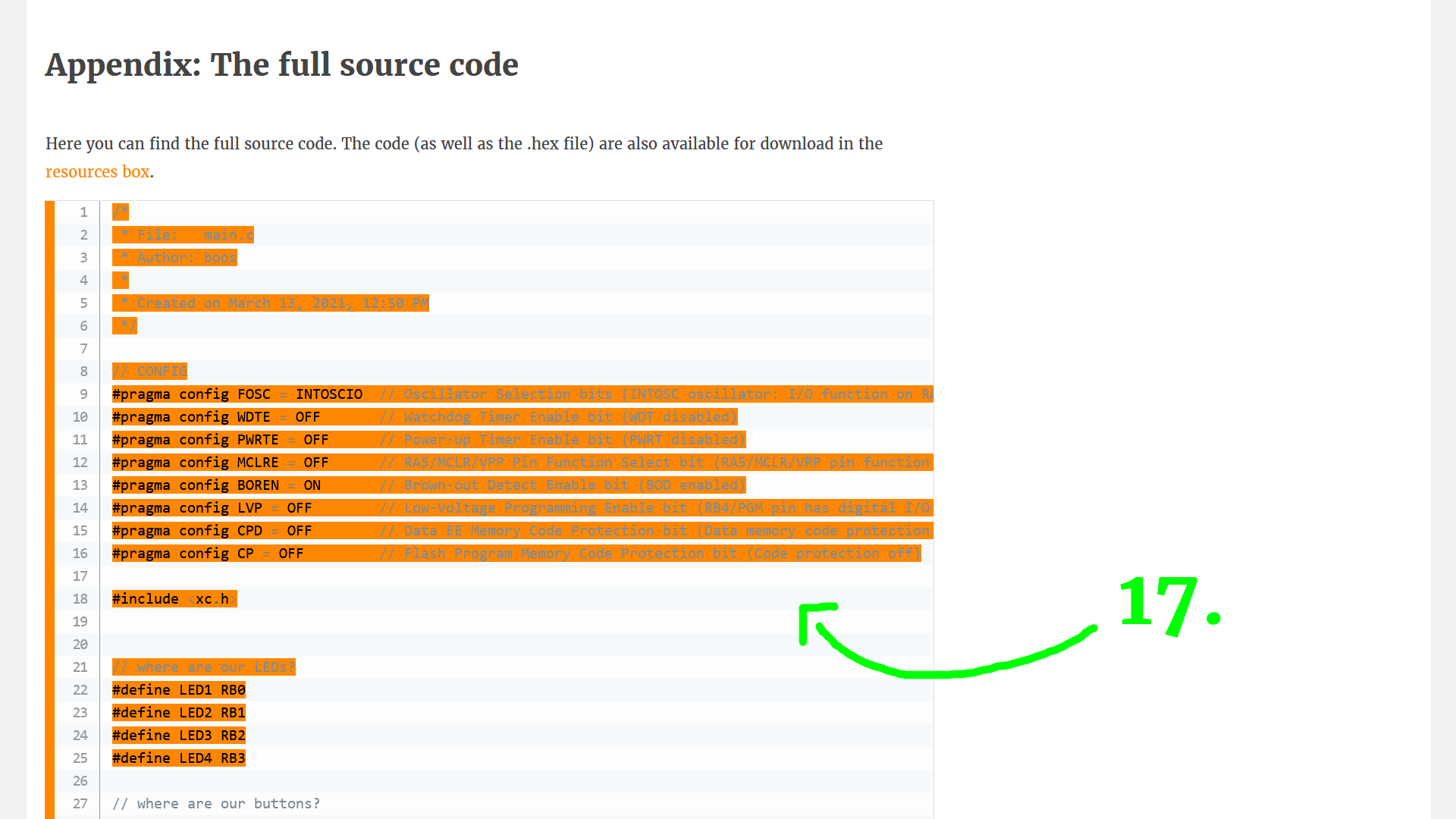
Then, copy & paste the entire source code from the appendix of this article:
Click the hammer symbol to compile the code (or press Shift + F11 if you prefer). This generates the .hex file:
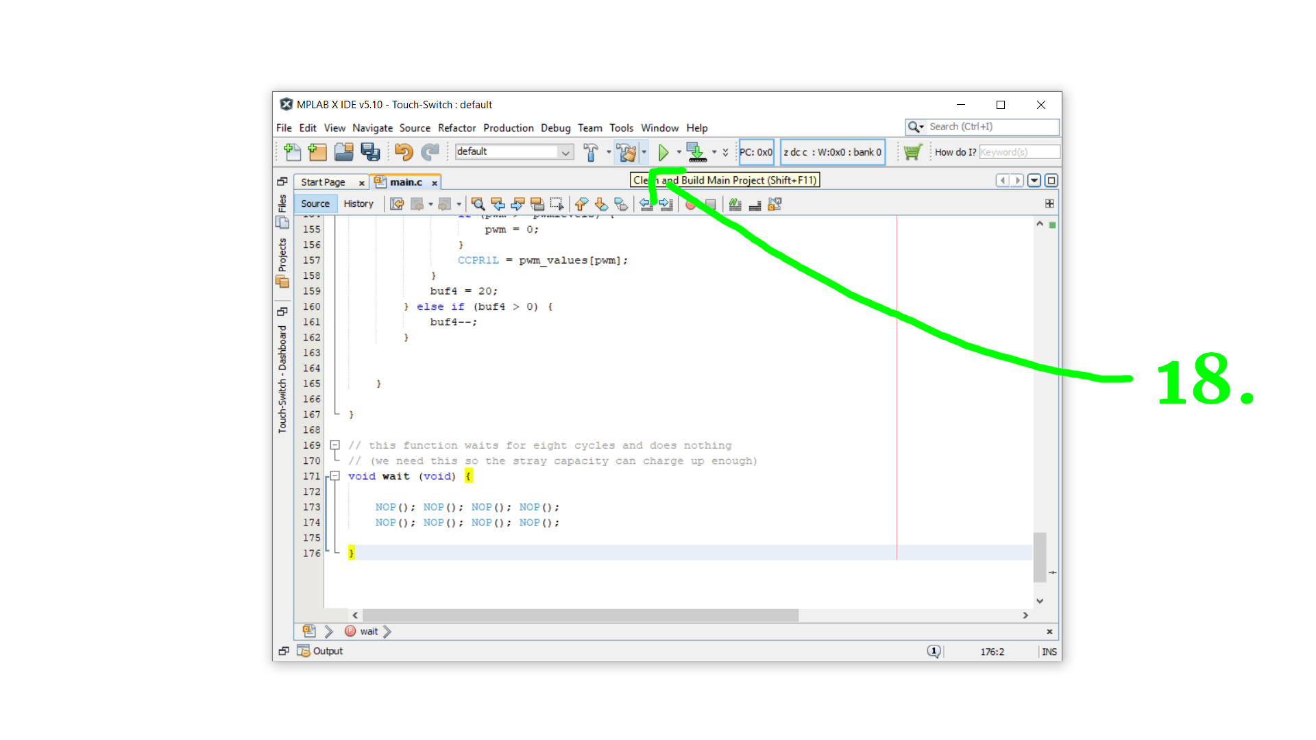
In the bottom dialog you should now see the green text BUILD SUCCESSFUL, and right after that you see the location of the .hex file. This is the file we need to transfer to the PIC16F627A later.

Okay, but what does the code that we just copied & pasted actually do? Let's have a look at it!
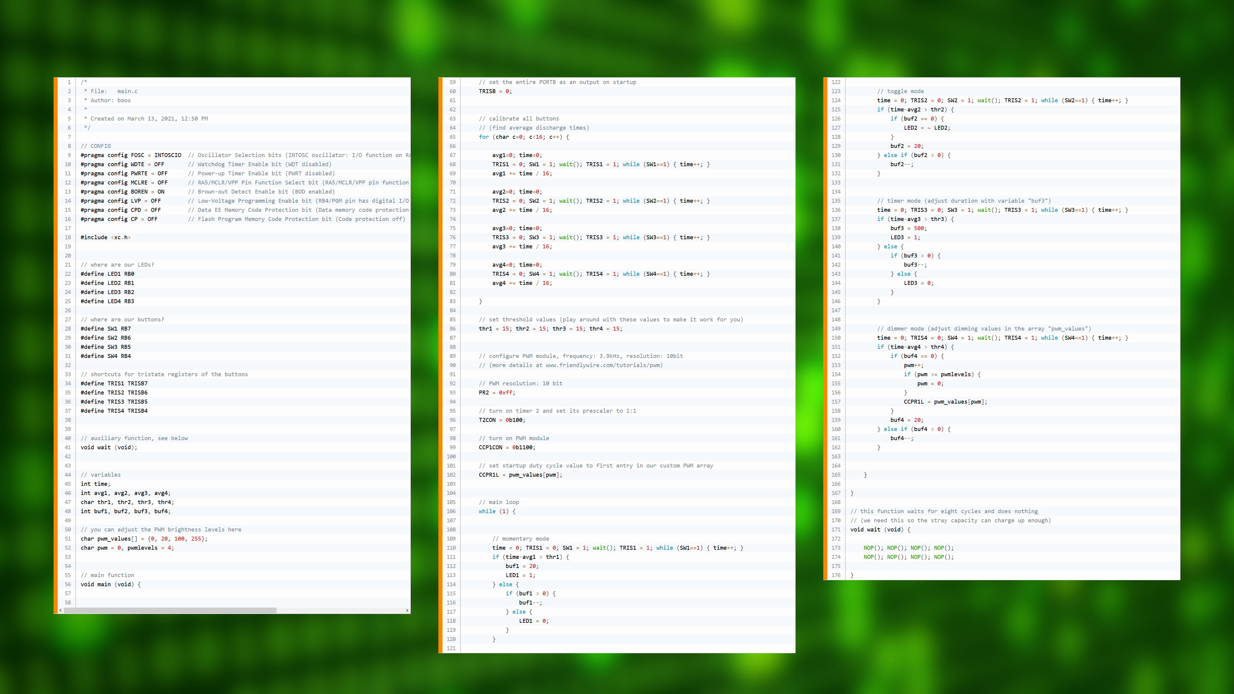
And as always it helps to split it into separate pieces:

Okay, but maybe you just want to know the main idea before going onto some sort of coding deep dive :) If yes, then here is the main idea. It's just one line!
time = 0; TRISB4 = 0; RB4 = 1; wait(); TRISB4 = 1; while (RB4==1) { time++; }This example is for the port RB4. The variable time is where we store how long it takes for the capacitor to discharge, so at the beginning we need to reset it. Then we set RB4 to be an output and set it high, so that it outputs VDD. To give the stray capacity some time to charge up, we then wait a bit. Then we set RB4 back to input mode, and in the while-loop wait until it reads back as a zero input. This happens as soon as the voltage at RB4 goes below 800mV (because it is a TTL input). And, while we're waiting, we increase the time variable. And that's it!
Okay, that was the main idea. But if you really want to learn how to program this yourself, then stick around :) If you cannot wait and want to get started with building the circuit then skip the next part and I will see you in the next chapter :)
(And I should also probably mention that I made a separate video about the C source code.)
In part #1 we set the configuration bits:
// CONFIG
#pragma config FOSC = INTOSCIO  // Oscillator Selection bits (INTOSC oscillator: I/O function on RA6/OSC2/CLKOUT pin, I/O function on RA7/OSC1/CLKIN)
#pragma config WDTE = OFF       // Watchdog Timer Enable bit (WDT disabled)
#pragma config PWRTE = OFF      // Power-up Timer Enable bit (PWRT disabled)
#pragma config MCLRE = OFF      // RA5/MCLR/VPP Pin Function Select bit (RA5/MCLR/VPP pin function is digital input, MCLR internally tied to VDD)
#pragma config BOREN = ON       // Brown-out Detect Enable bit (BOD enabled)
#pragma config LVP = OFF        // Low-Voltage Programming Enable bit (RB4/PGM pin has digital I/O function, HV on MCLR must be used for programming)
#pragma config CPD = OFF        // Data EE Memory Code Protection bit (Data memory code protection off)
#pragma config CP = OFF         // Flash Program Memory Code Protection bit (Code protection off)

#include <xc.h>
The only important lines are 9 (where we turn on the internal 4MHz oscillator so that we don't need an external one) and line 14 where we disable low-voltage programming (so that we only need three wires to flash the PIC later).
Then, in part #2, to make our life simpler we define a couple of abbreviations: for each switch we define its location, its tri-state register, and its corresponding LED. This is completely optional but makes the rest of the program easier to read and easier to change later on, if you ever want to:
// where are our LEDs?
#define LED1 RB0
#define LED2 RB1
#define LED3 RB2
#define LED4 RB3

// where are our buttons?
#define SW1 RB7
#define SW2 RB6
#define SW3 RB5
#define SW4 RB4

// shortcuts for tristate registers of the buttons
#define TRIS1 TRISB7
#define TRIS2 TRISB6
#define TRIS3 TRISB5
#define TRIS4 TRISB4
Now we can just write LED1 instead of RB0, and so on. Next, in part #3, we define our variables:
// auxiliary function, see below
void wait (void);


// variables
int time;
int avg1, avg2, avg3, avg4;
char thr1, thr2, thr3, thr4;
int buf1, buf2, buf3, buf4;

// you can adjust the PWM brightness levels here
char pwm_values[] = {0, 20, 100, 255};
char pwm = 0, pwmlevels = 4;
Line 41 is a prototype or declaration for an auxiliary function that I call wait(). We will get back to that one in part #10, but we need to declare it at that point so that the XC8 compiler knows that it exists.
The variables are all very similar, with the last digit telling us for which button we defined them. avg1 stores the average discharge time of button 1, thr1 is for the threshold beyond which we want to think of button 1 as pressed, and buf1 is an auxiliary buffer variable that we can use to debounce our switch.
The variables in lines 51 and 52 are for the dimming functionality; the array pwm_values[] stores the brightness levels, where a 0 is completely off and 255 is completely on. Feel free to add more stages, if you want, only remember to set the variable pwmlevels to the number of brightness values in the array.
All of this was done in the first part of the program. Now the main-function begins in line 56, and this function contains, well, the main part of the program. And the function ends in line 163, just so you know. Everything in between is part of the main function.
// main function
void main (void) {}Okay, so what does the main function do? Here is the first part:
    // set the entire PORTB as an output on startup
    TRISB = 0;


    // calibrate all buttons
    // (find average discharge times)
    for (char c=0; c<16; c++) {

        avg1=0; time=0;
        TRIS1 = 0; SW1 = 1; wait(); TRIS1 = 1; while (SW1==1) { time++; }
        avg1 += time / 16;

        avg2=0; time=0;
        TRIS2 = 0; SW2 = 1; wait(); TRIS2 = 1; while (SW2==1) { time++; }
        avg2 += time / 16;

        avg3=0; time=0;
        TRIS3 = 0; SW3 = 1; wait(); TRIS3 = 1; while (SW3==1) { time++; }
        avg3 += time / 16;

        avg4=0; time=0;
        TRIS4 = 0; SW4 = 1; wait(); TRIS4 = 1; while (SW4==1) { time++; }
        avg4 += time / 16;

    }

    // set threshold values (play around with these values to make it work for you)
    thr1 = 15; thr2 = 15; thr3 = 15; thr4 = 15;
In the first part, it mostly sets up things that we need later. In line 60 it sets the entire PORTB as an output. This is done so that all LEDs can be turned on and off. (The other tristate registers for the switches will be, well, switched between input and output mode later on, so line 60 is not important for them.)
Then, in lines 65–83, we calibrate our buttons by measuring the discharge time for each one of them sixteen times in total. The measuring is done in lines 68, 72, 76, and 80, and it uses the one-liner we already talked about before. After each of these measurements, it adds one sixteenth of it to the average value. we use 16 here instead of 10 or 15 because it is a power of 2: a division by 16 is computationally very cheap and it just means that all bits move four to the right. And last, in line 86, we also set the threshold values to 15, and this is a value that works well when I built the circuit here for myself, but it might be slightly different in your case, so feel free to experiment with those values :)
Next, because one of our switches uses the PWM module to dim an LED, we need to set up the PIC16F627A's PWM module. This is the only part of the code that is truly controller-specific. We are setting it to 3.9kHz (because the PIC16F627A runs at 4MHz via its internal oscillator) at a PWM resolution of 10 bit, and we already learned about that kind of stuff in the PWM tutorial:
    // configure PWM module, frequency: 3.9kHz, resolution: 10bit
    // (more details at www.friendlywire.com/tutorials/pwm)

    // PWM resolution: 10 bit
    PR2 = 0xff;

    // turn on timer 2 and set its prescaler to 1:1
	T2CON = 0b100;

    // turn on PWM module
	CCP1CON = 0b1100;

    // set startup duty cycle value to first entry in our custom PWM array
	CCPR1L = pwm_values[pwm];
In the last line, we set the default duty-cycle value. Because the variable pwm is equal to zero upon startup, and because the first entry of the array pwm_values[] is zero (for both: see line 52), the duty cycle is zero on startup, meaning that LED3 is turned off. But hey, that's the nice thing about programming it yourself: you can change it to whatever you like :)
With the calibration out of the way, we now enter the main loop in part #7. This main loop is the main structure of the program, and it will keep running and running until you disconnect the power. This is a very common structure for microcontroller programs.
    // main loop
while (1) { }And, just to be complete, this loop closes again in line 165.
Inside the loop we check the four buttons, one after each other. We first measure their discharge time. But because they all do slightly different things (momentary switch, toggle switch, timer, and dimmer) the following pieces of code all look a little bit different.
In part #8a we check button 1 in momentary mode:
        // momentary mode
        time = 0; TRIS1 = 0; SW1 = 1; wait(); TRIS1 = 1; while (SW1==1) { time++; }
        if (time-avg1 > thr1) {
            buf1 = 20;
            LED1 = 1;
        } else {
            if (buf1 > 0) {
                buf1--;
            } else {
                LED1 = 0;
            }
        }
Line 110 simply measures the discharge time, just as we did during calibration. Then, in line 111, we check if the difference between the measured discharge time and the average discharge time is larger than the critical threshold. If yes, then we know somebody has touched the button and we turn LED1 on.
The parts with the variable buf1 look a bit confusing. But its purpose is very simple: we just want the button to register as “not pressed” 20 times in a row until we are willing to turn the LED off again. This makes sure that the button does not vary rapidly when you are moving your finger away from the button and basically debounces the button.
In part #8b we check button 2 in toggle mode:
        // toggle mode
        time = 0; TRIS2 = 0; SW2 = 1; wait(); TRIS2 = 1; while (SW2==1) { time++; }
        if (time-avg2 > thr2) {
            if (buf2 == 0) {
                LED2 = ~ LED2;
            }
            buf2 = 20;
        } else if (buf2 > 0) {
            buf2--;
        }
Line 124 measures the discharge time, and if somebody pressed the button we toggle LED2 (line 127). The variable buf2 is used to make sure that we have to leave the button alone for 20 cycles for it to be toggled again. This is a similar idea to the debouncing we just talked about for button 1, and it just makes the button behave more stable. Give it a try yourself and change the numbers :)
In part #8c we check button 3 in timer mode:
        // timer mode (adjust duration with variable "buf3")
        time = 0; TRIS3 = 0; SW3 = 1; wait(); TRIS3 = 1; while (SW3==1) { time++; }
        if (time-avg3 > thr3) {
            buf3 = 500;
            LED3 = 1;
        } else {
            if (buf3 > 0) {
                buf3--;
            } else {
                LED3 = 0;
            }
        }
As you can see by comparing this to button 1, the code is identical to it, except for line 138. We use a very large value for buf3 so that the button stays on a maximum of 500 cycles after you stop touching it, and because this number is large we actually notice it as a time delay.
And last, in part #8d we check button 4 in dimmer mode:
        // dimmer mode (adjust dimming values in the array "pwm_values")
        time = 0; TRIS4 = 0; SW4 = 1; wait(); TRIS4 = 1; while (SW4==1) { time++; }
        if (time-avg4 > thr4) {
            if (buf4 == 0) {
                pwm++;
                if (pwm >= pwmlevels) {
                    pwm = 0;
                }
                CCPR1L = pwm_values[pwm];
            }
            buf4 = 20;
        } else if (buf4 > 0) {
            buf4--;
        }
Whenever the button is read as pressed, we increment the variable pwm to cycle through the different dimmer values which are stored in the array pwm_values[]. The variable buf4 again serves as a debouncing variable.
Then, in part #9, the main loop and the main function end, and we are left with the last piece, part #10. This is our wait() function:
// this function waits for eight cycles and does nothing
// (we need this so the stray capacity can charge up enough)
void wait (void) {

    NOP(); NOP(); NOP(); NOP();
    NOP(); NOP(); NOP(); NOP();

}
What it does is very simple: it calls the command NOP(); eight times. NOP stands for “no operation” and it basically makes the controller idle for one clock cycle. We need this function to make sure that the stray capacities have enough time to charge up.
And that's it! The last thing we need to do is take this code and compile it into a .hex file. If you want to build this project exactly as-is then you can download the .hex file in the resources box of this article. Put that file aside because later we need to flash it onto the controller. But before we can do that, we need to build the circuit first :)
Building the circuit
To those of you that went through the program explanation: you made it! And to everybody else: welcome back :) So now let's get started with building the circuit!
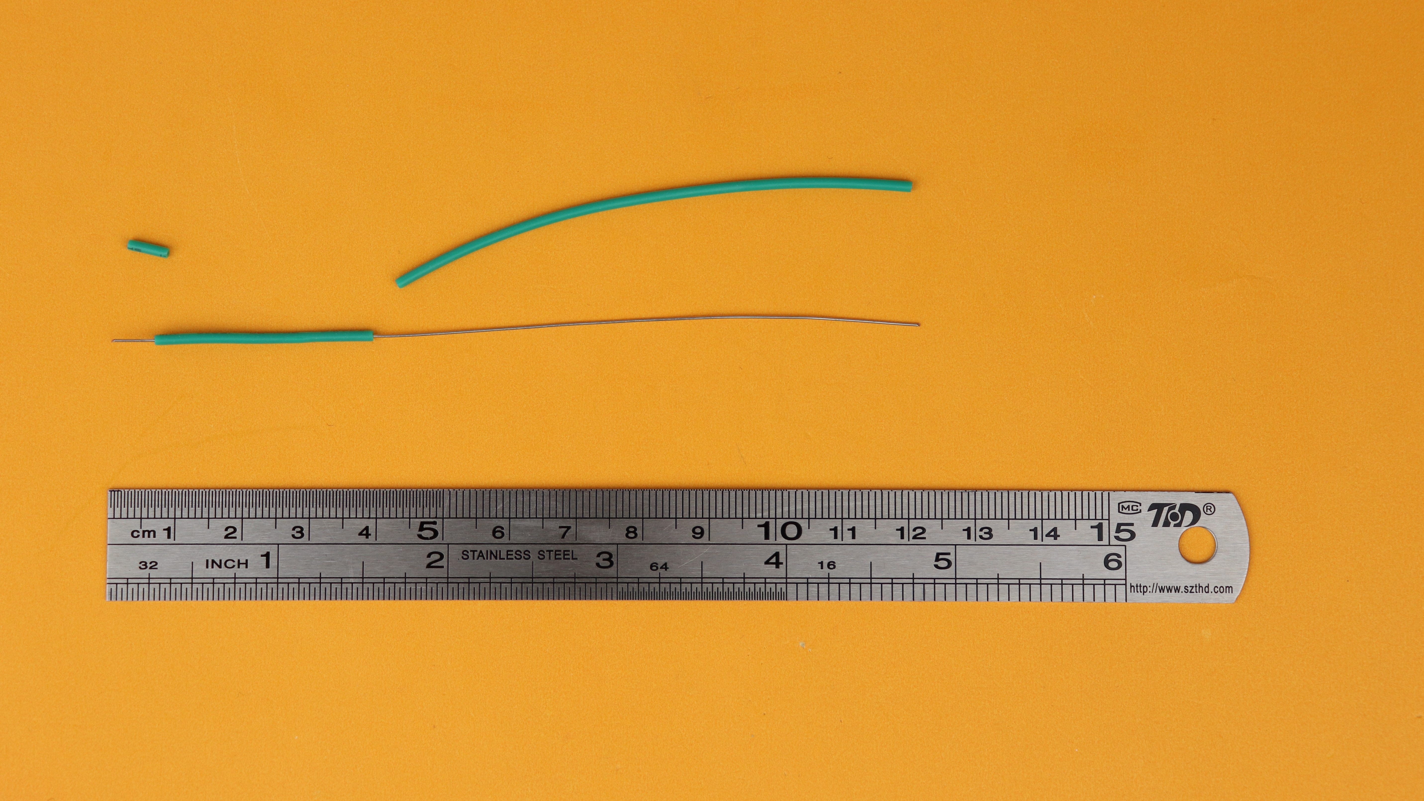
First we need to make the touch sensors. This is very easy, just use a 12cm wire and remove around 8cm of the isolation on the one side, and 0.5cm on the other side:
Then, using some pliers, wrap the long end into circles:
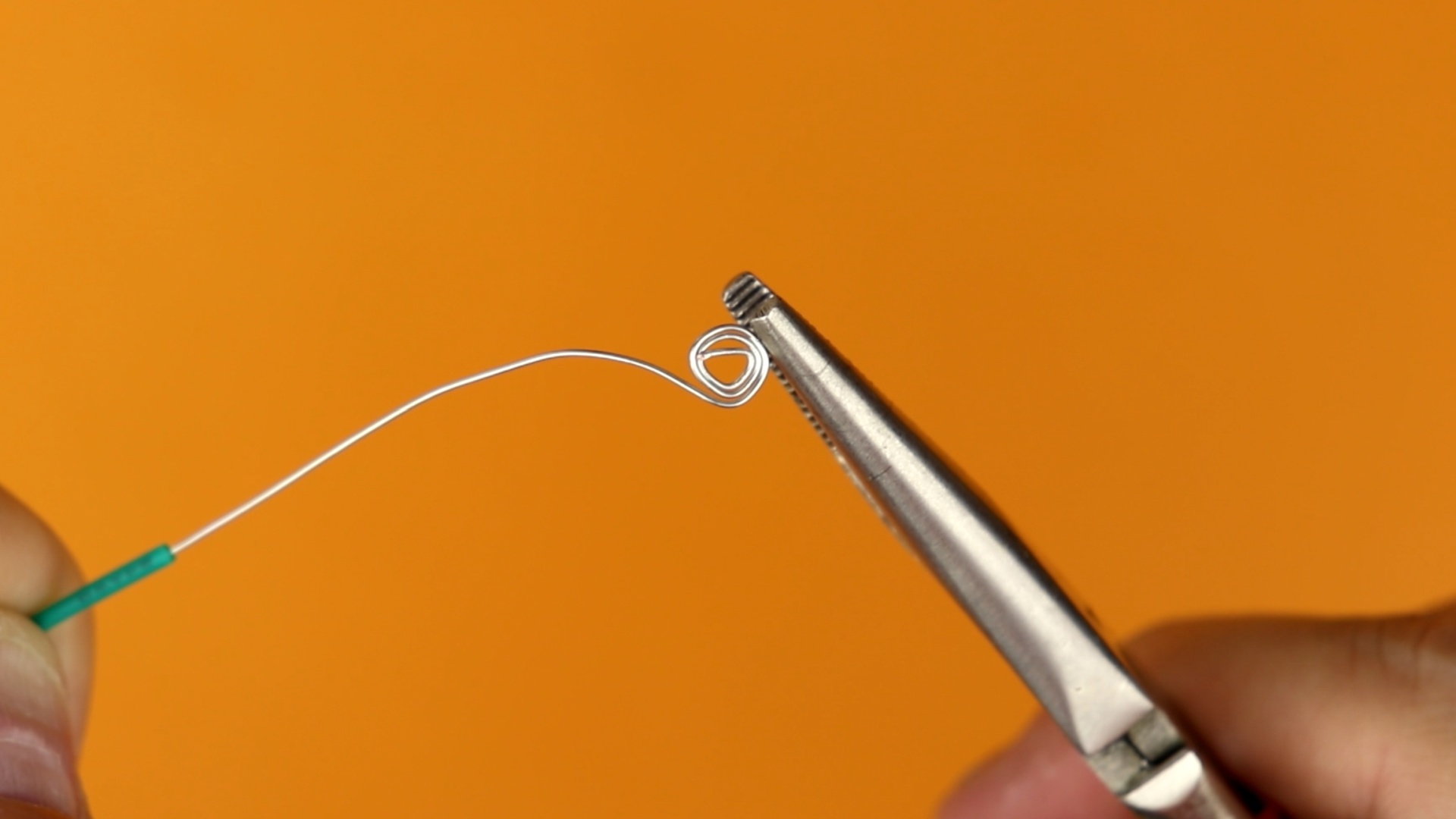
At the end, the finished sensor should look something like that:

And now we can get started on building the circuit on the breadboard. Let's go!
-
-
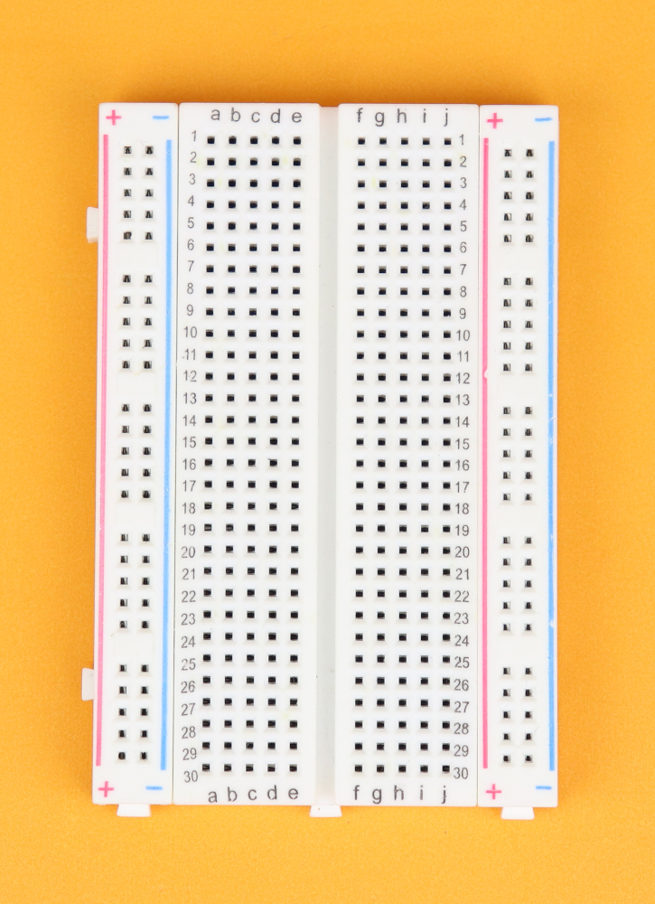
Step 1
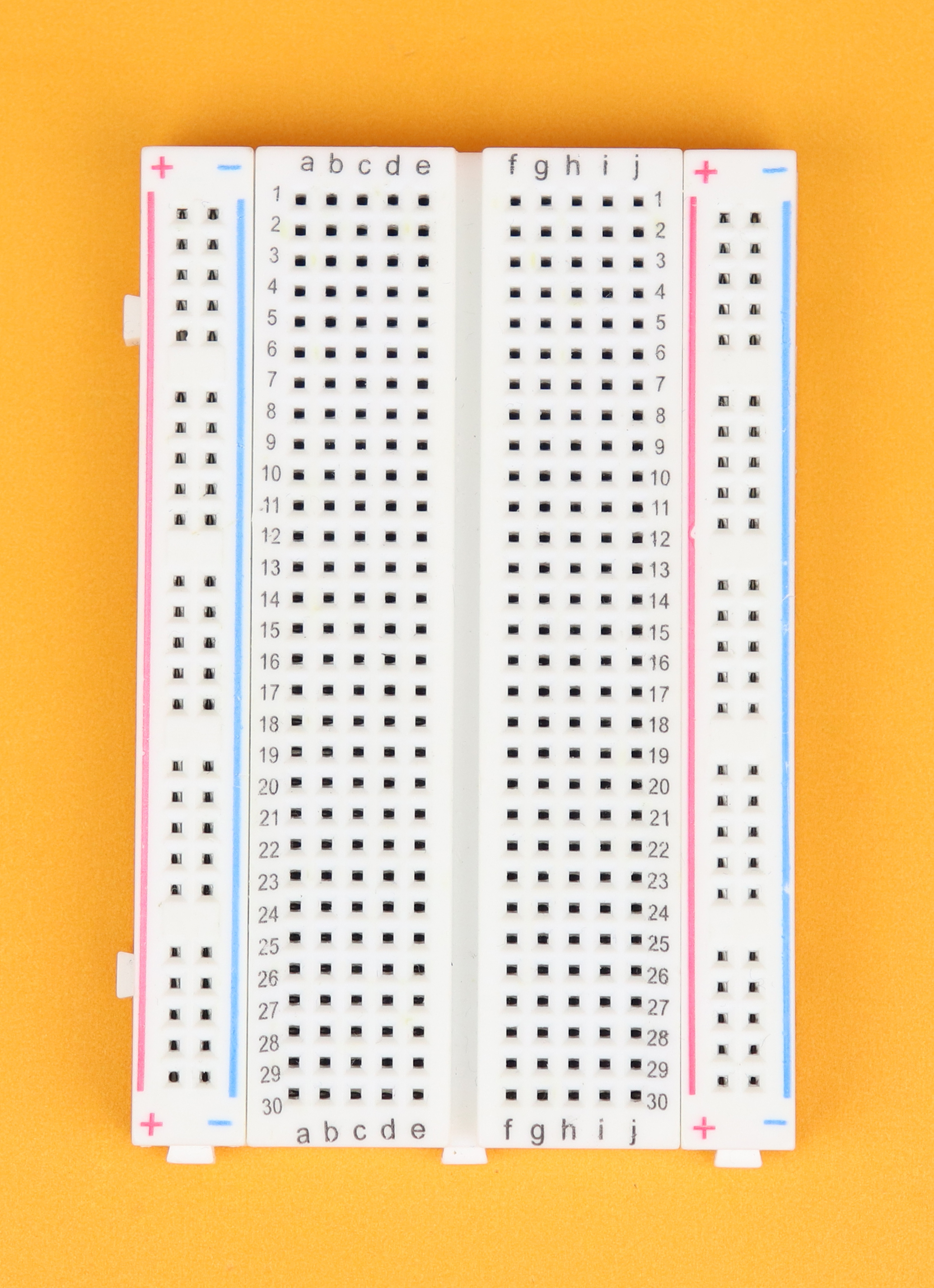
Place the breadboard in front of you, with row 1 facing to the top.
-
-
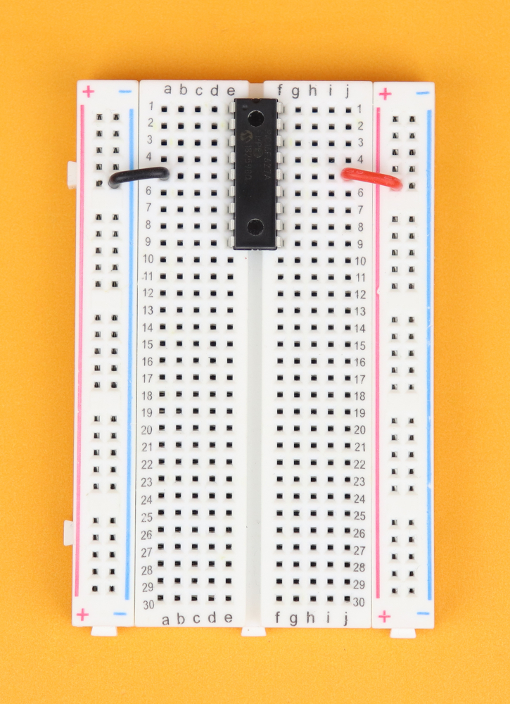
Step 2
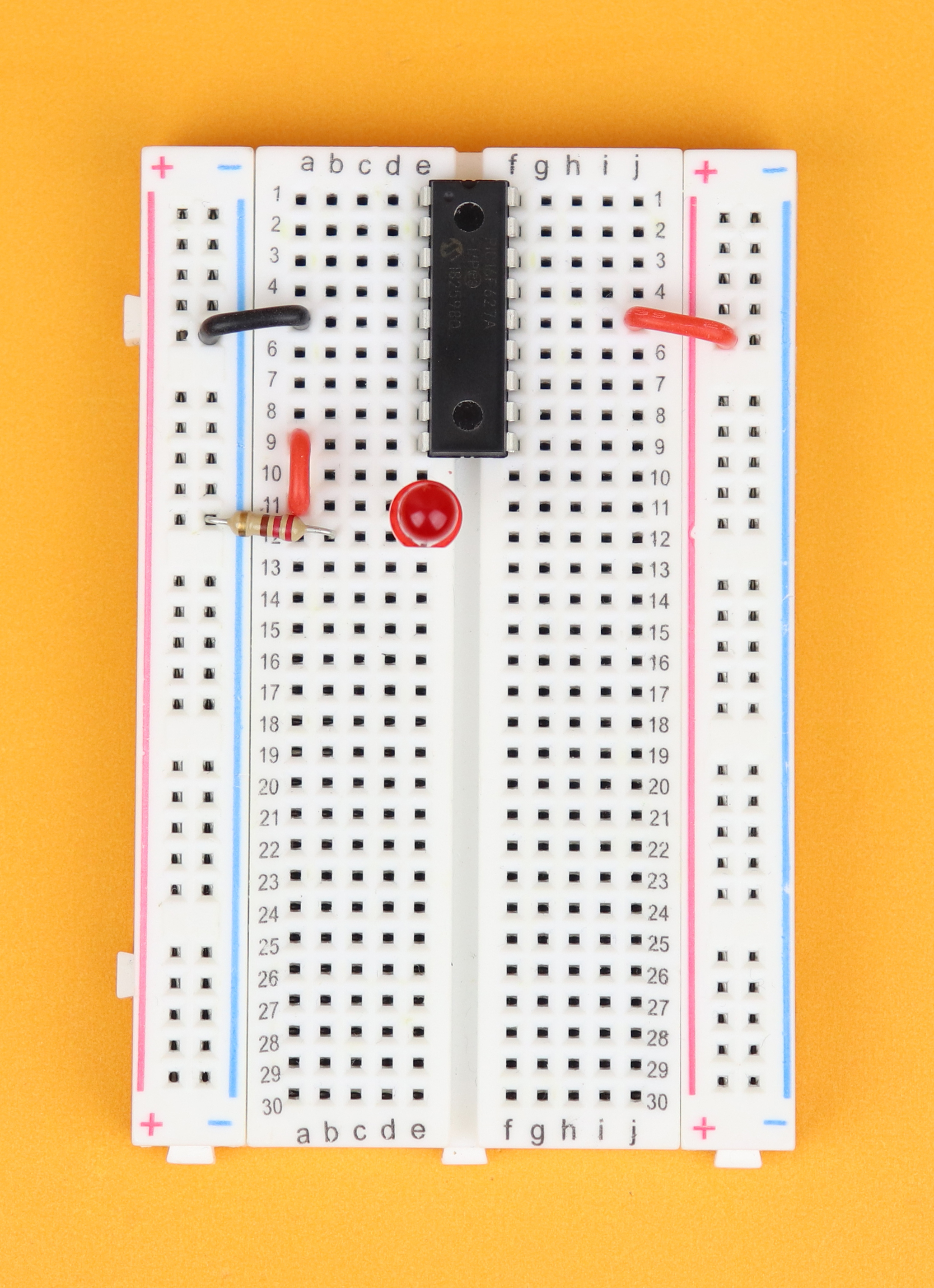
Insert the PIC16F627A in row 1, and make sure the notch points to the top. Connect VDD at pin 14 to the positive power rail on the right, and ground at pin 5 to the ground rail on the left.
-

-
Step 3
Connect row 9 to 11 on the left, insert R4 between row 12 and ground, and then insert LED4 in between (with its negative terminal in row 12).
-
-
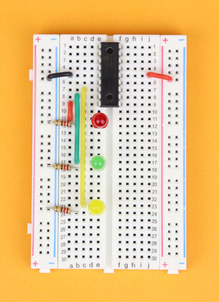
Step 4
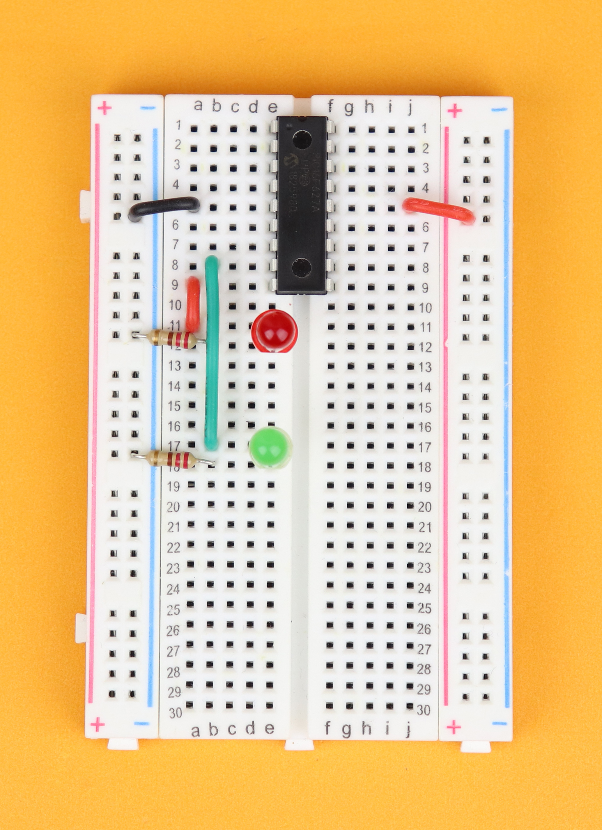
Connect row 8 to 17 on the left, insert R3 between row 18 and ground, and then insert LED3 in between (with its negative terminal in row 18).
-
-
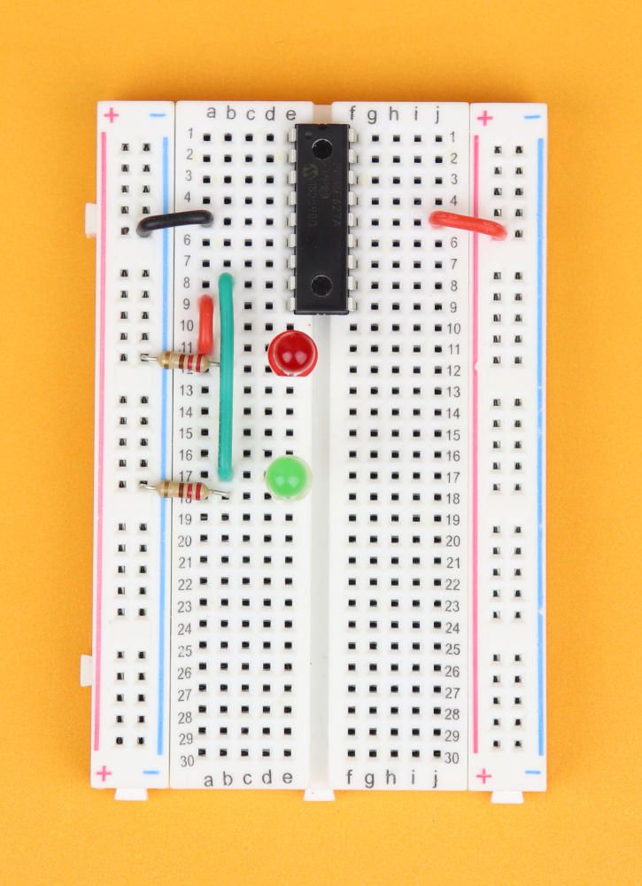
Step 5
Connect row 7 to 23 on the left, insert R2 between row 24 and ground, and then insert LED2 in between (with its negative terminal in row 24).
-
-
Step 6
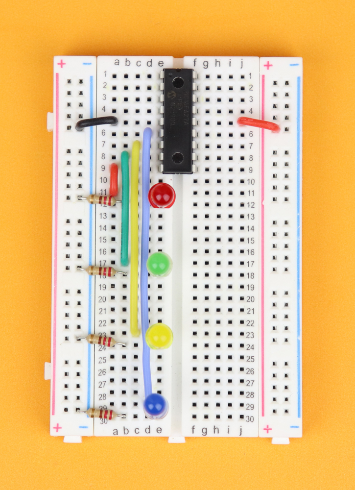
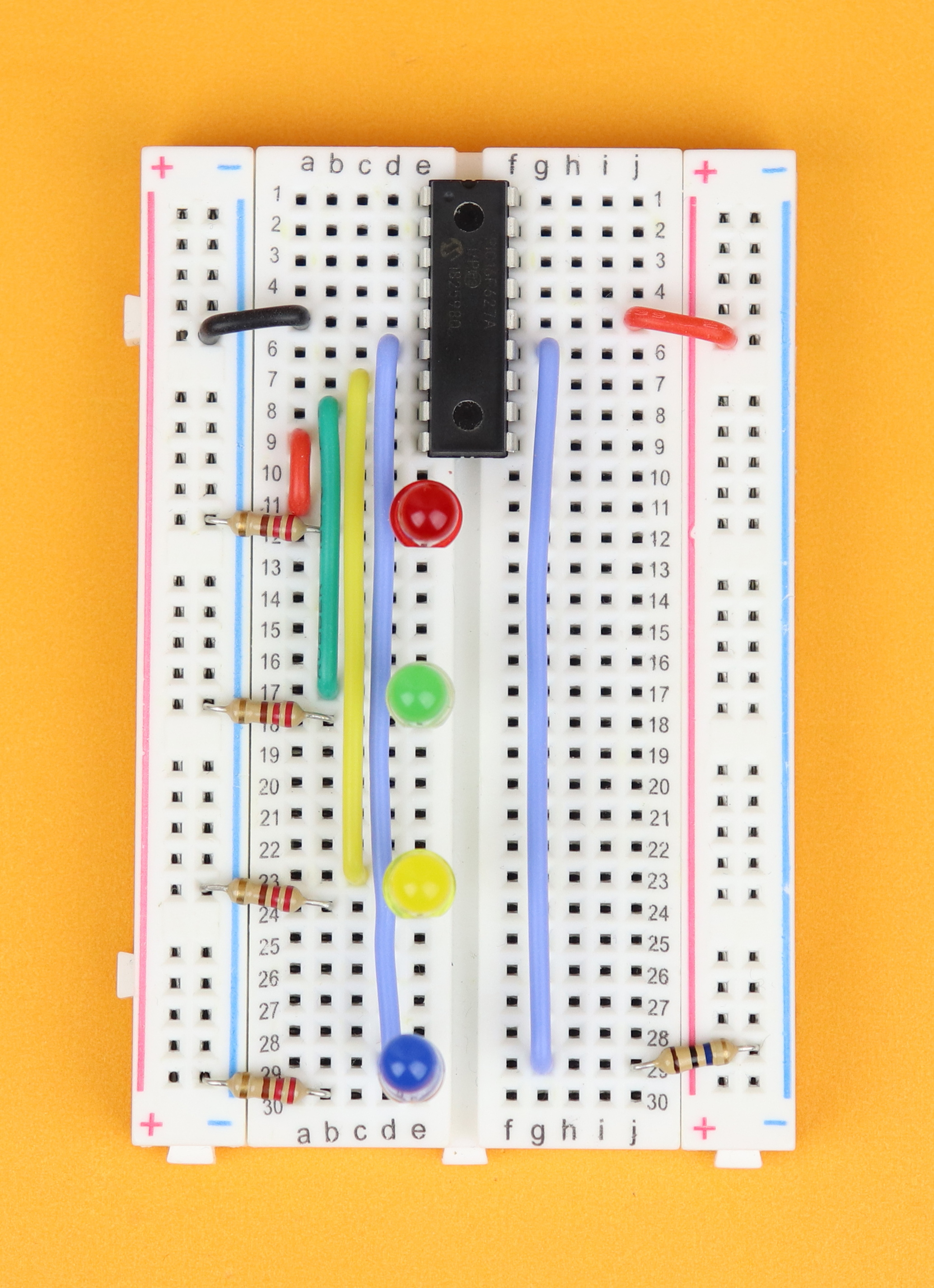
Connect row 6 to 29 on the left, insert R1 between row 30 and ground, and then insert LED1 in between (with its negative terminal in row 30).
-
-
Step 7
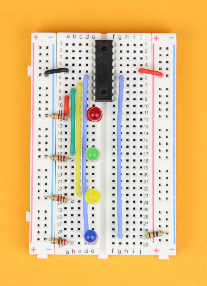
Connect row 6 to 29 on the right and insert R5 between row 29 and ground.
-

-
Step 8
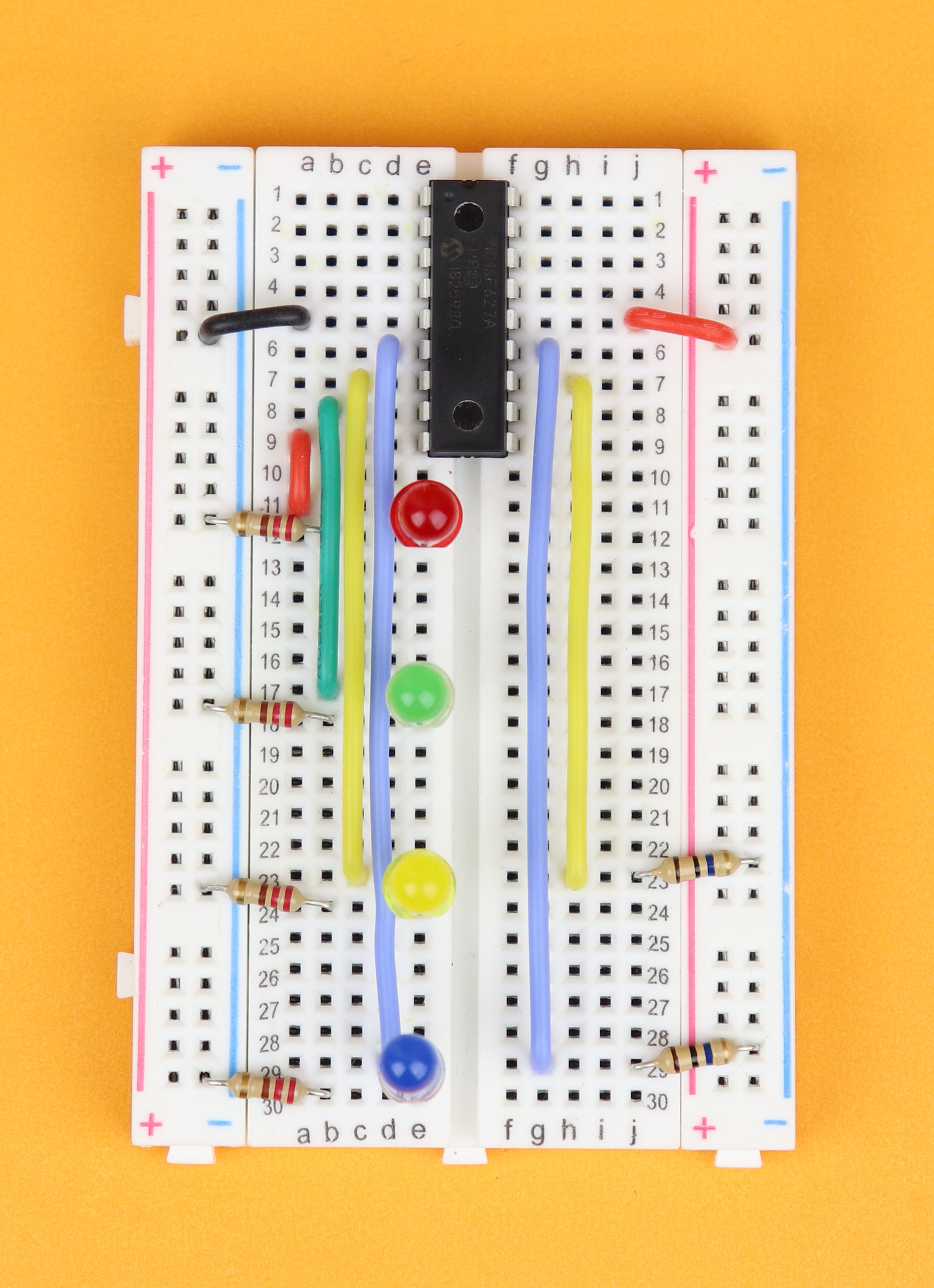
Connect row 7 to 23 on the right and insert R6 from the same row to ground.
-

-
Step 9
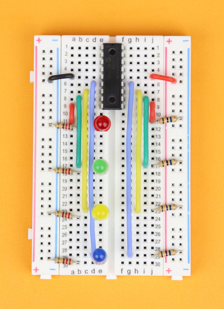
Connect row 8 to 17 on the right and insert R7 from the same row to ground.
-
-
Step 10
Connect row 9 to 11 on the right and insert R8 from the same row to ground.
-

-
Step 11
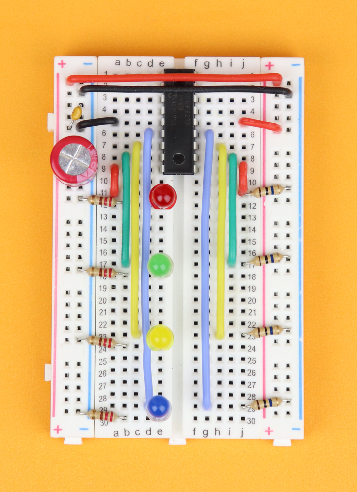
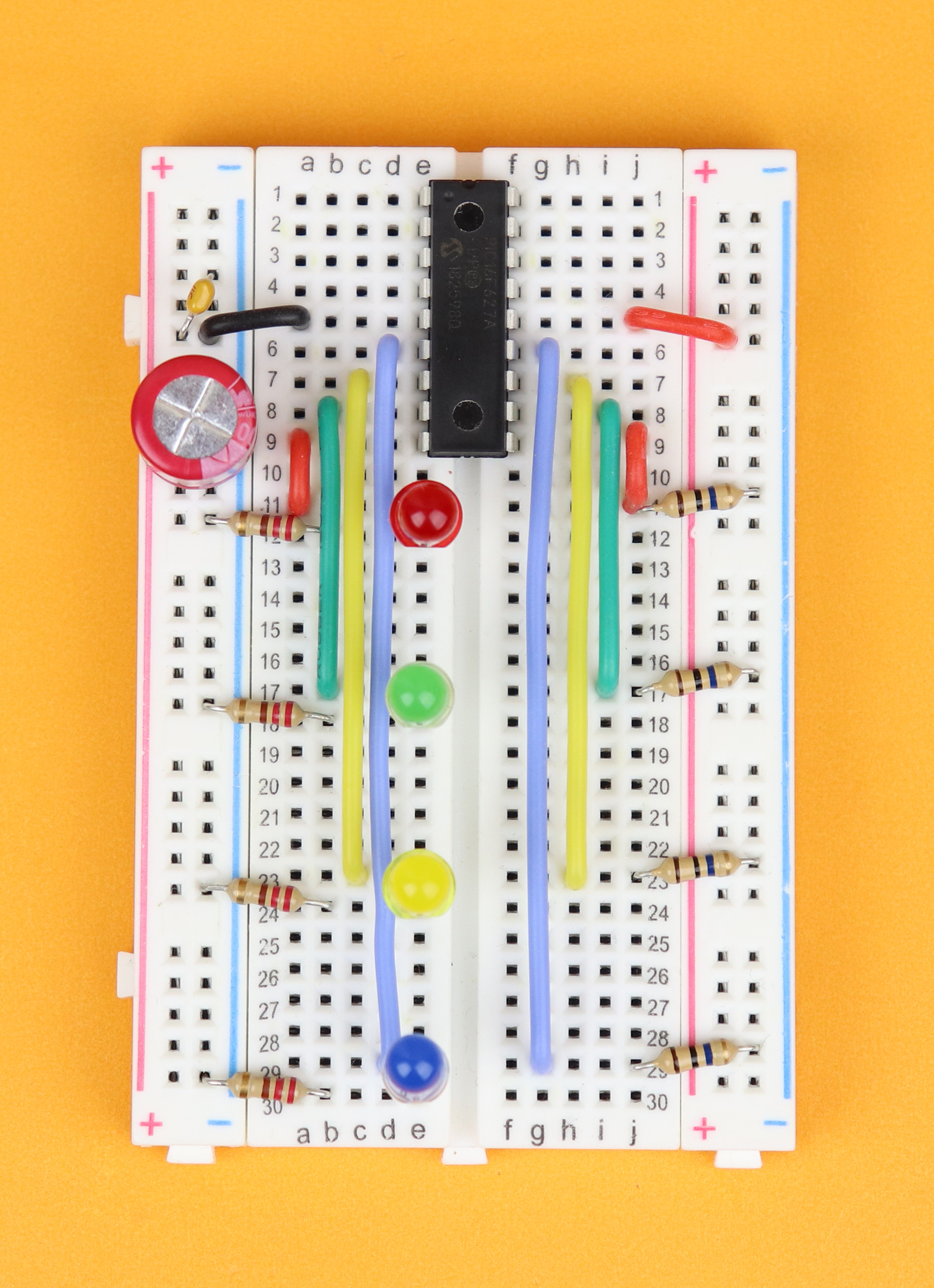
Insert the 100μF capacitor C1 in the power rail, and make sure its negative terminal (the one with the big minus sign) plugs into the negative power rail. Then, insert C2 in the power rail as well, and this one can go in either way.
-
-
Step 12
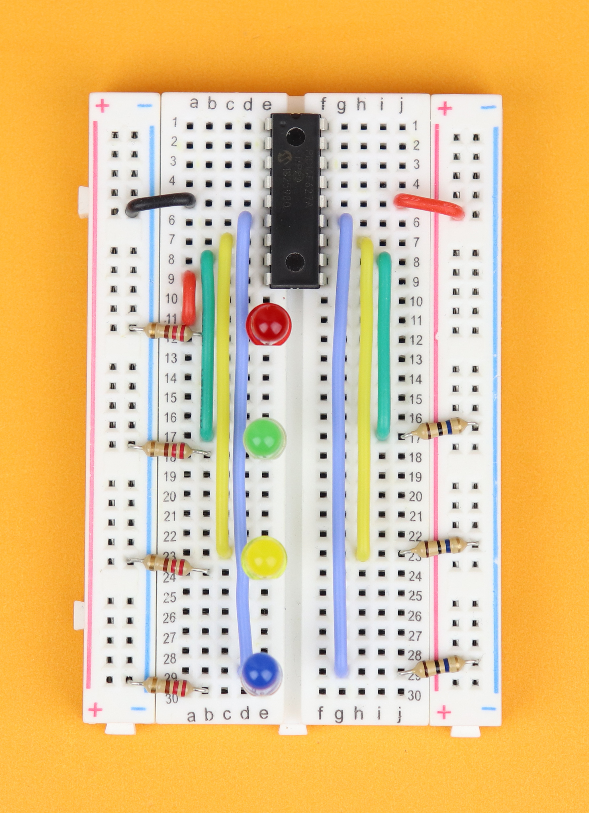
Connect the positive and negative power rails to each other on both sides of the breadboard.
-
-
Step 13
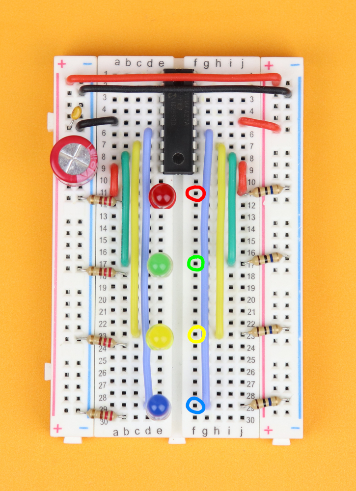
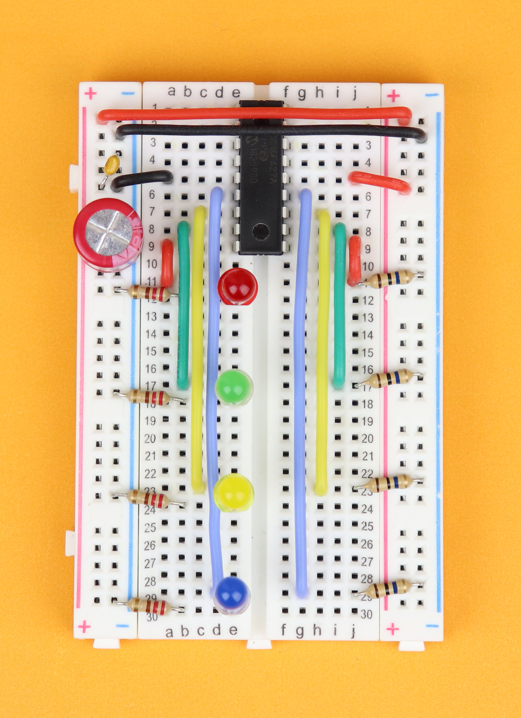
Now it's time to insert the touch sensor wires, and in the picture you can see the colored circles that indicate where each wire goes.
-

-
Step 14
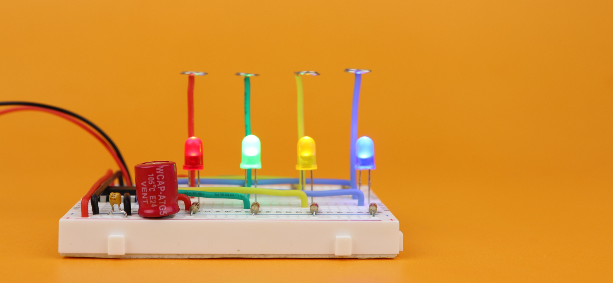
...and this is how it looks like with all four touch sensor wires installed in rows 11, 17, 23, and 29.
-

-
Step 15
And last, connect the 4.5V battery pack to the power rail (the red wire to the positive power rail, and the black wire to the negative power rail).


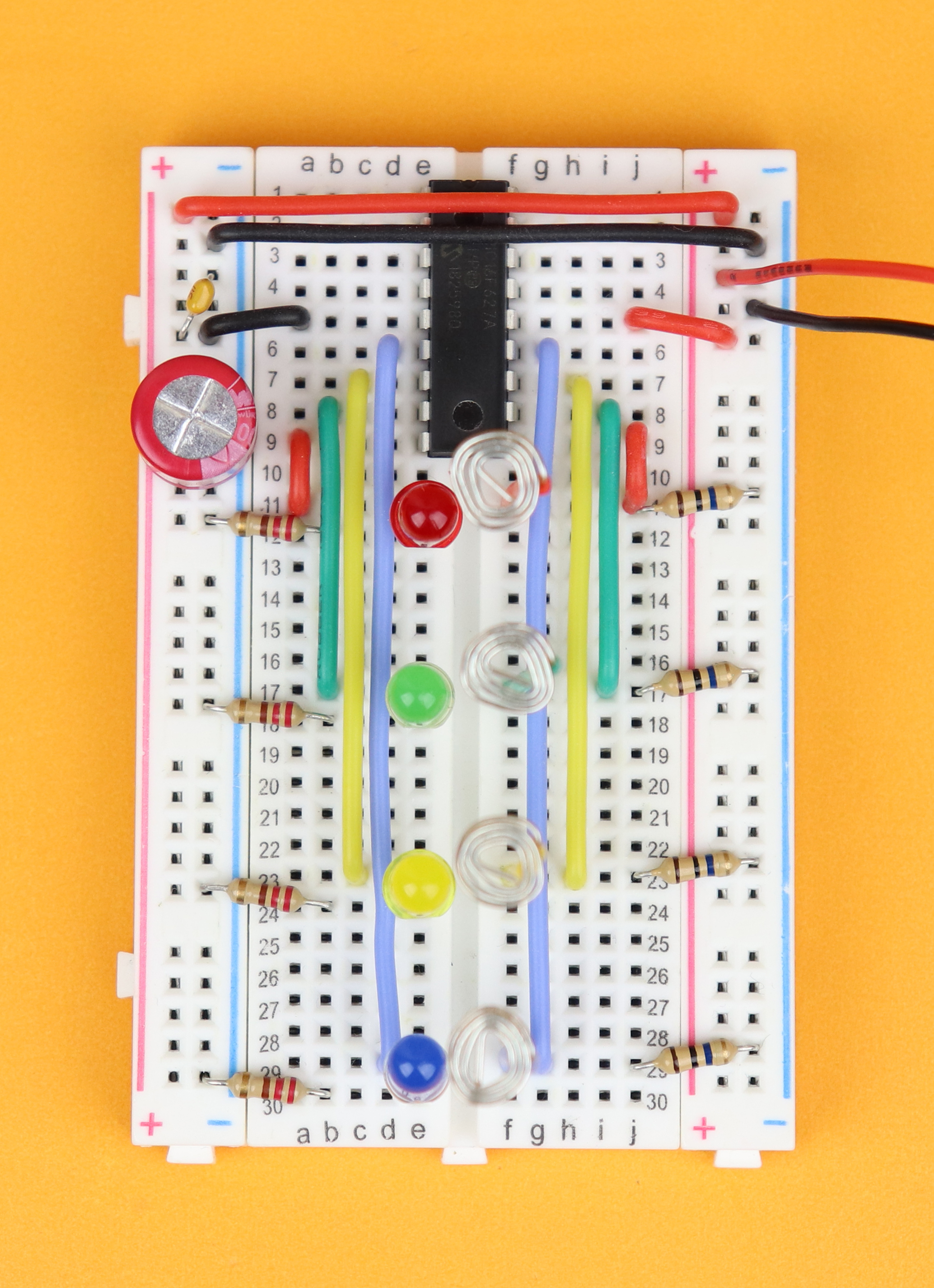
And this is how it looks like:

Of course nothing happens yet when you plug in the power because the controller does not have any program on it yet, so it doesn't know what to do: we need to “flash” the controller first! So let's do that next :)
Flashing the controller
Remember the .hex file that we created in the MPLAB X IDE? Now it's time to put it on the PIC16F627A. And to flash the .hex file onto the controller, we need to connect the PIC16F627A to the PICkit3. Here is how we do that:
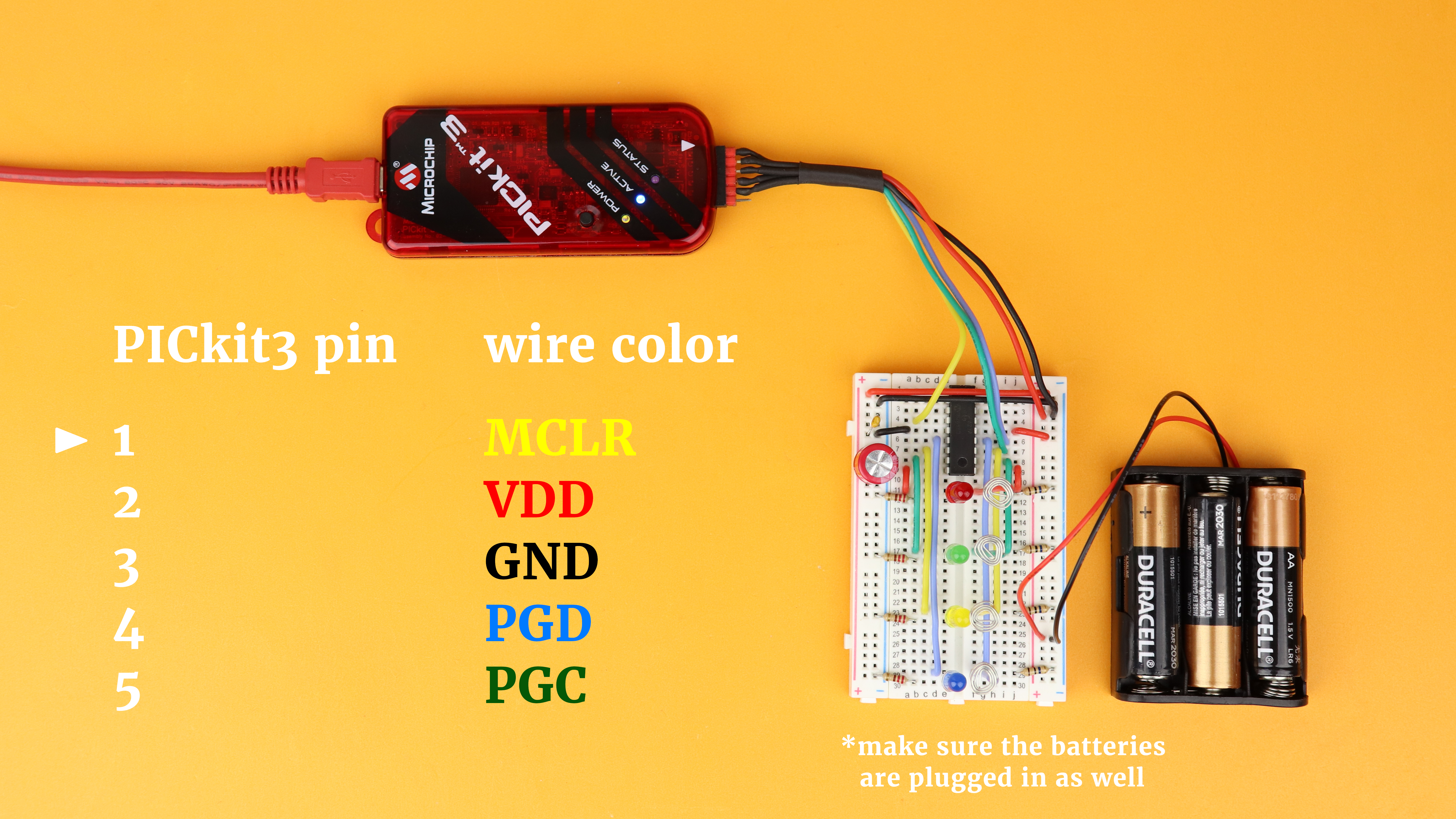
The PICkit3 has five terminals that we need to connect to the circuit. VDD (pin 2 of the PICkit3) and GND (pin 3 of the PICkit3) can be connected to the power rail. The other pins are connected like this:
- MCLR (master clear) at pin 1 of the PICkit3 is connected to pin 4 of the PIC16F627A.
- PGD (program data) at pin 4 of the PICkit3 is connected to pin 13 of the PIC16F627A.
- PGC (program clock) at pin 5 of the PICkit3 is connected to pin 12 of the PIC16F627A.
- PGM (program mode) is left unconnected.
And here is how it looks like in real life:
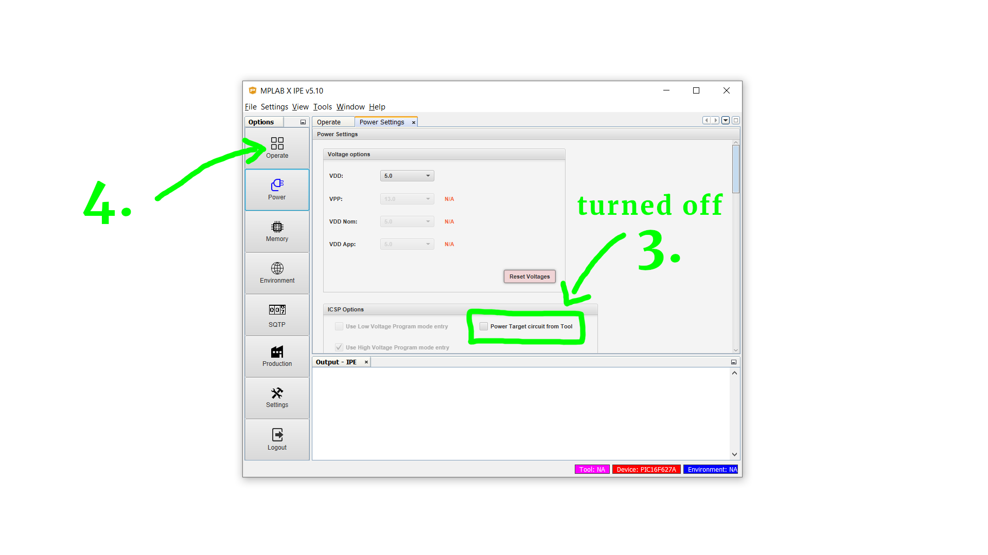
The other USB end is plugged into your computer. Then we need to open the MPLAB IPE (which is part of the MPLAB IDE installation). Under Device select PIC16F627A and under Tool select PICkit3. Then click the Power tab:

In the Power tab make sure that the option “Power target circuit from tool” is turned off, and click back on Operate.
Now you can click on Connect...
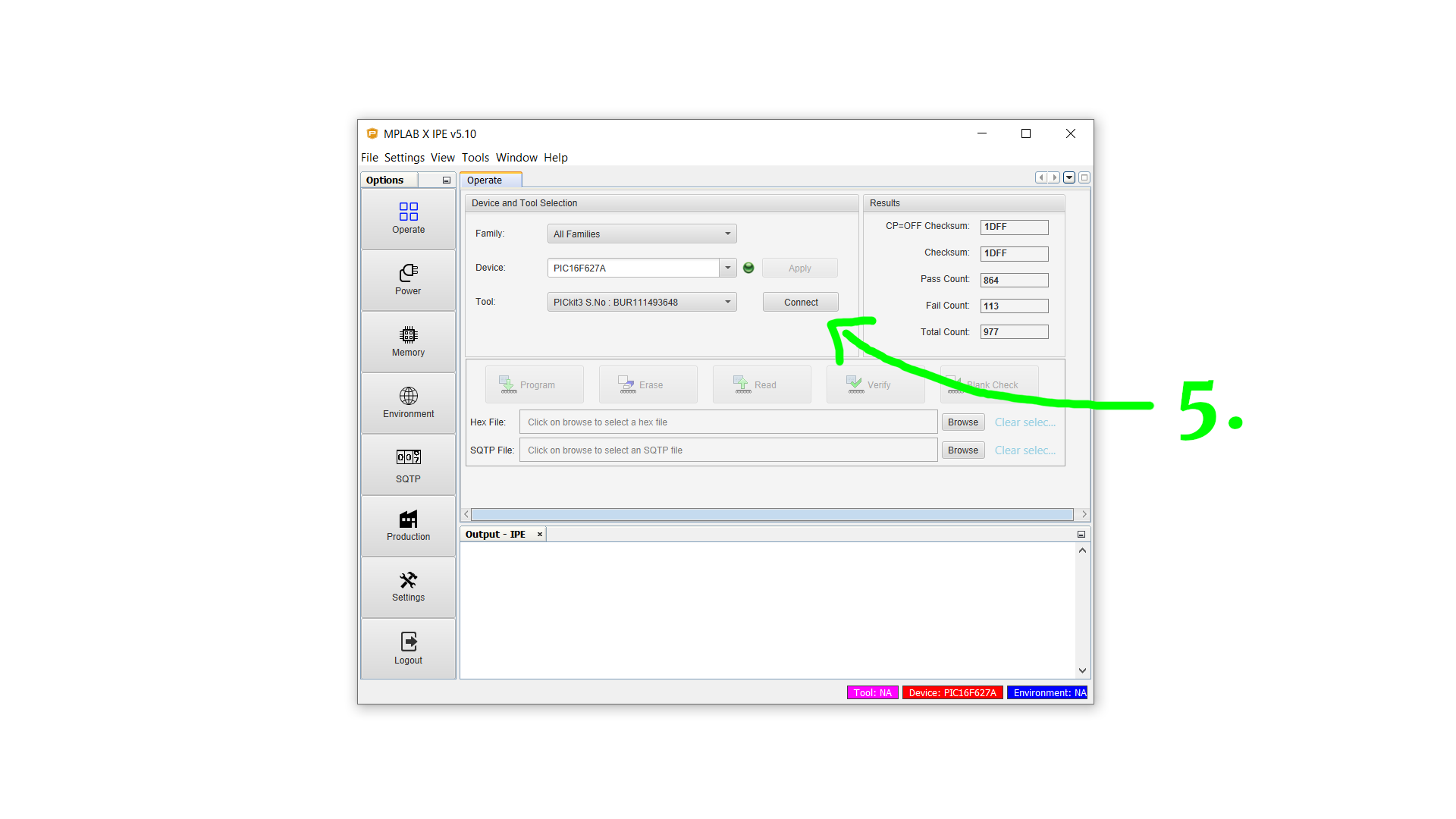
...and confirm this dialog with OK.

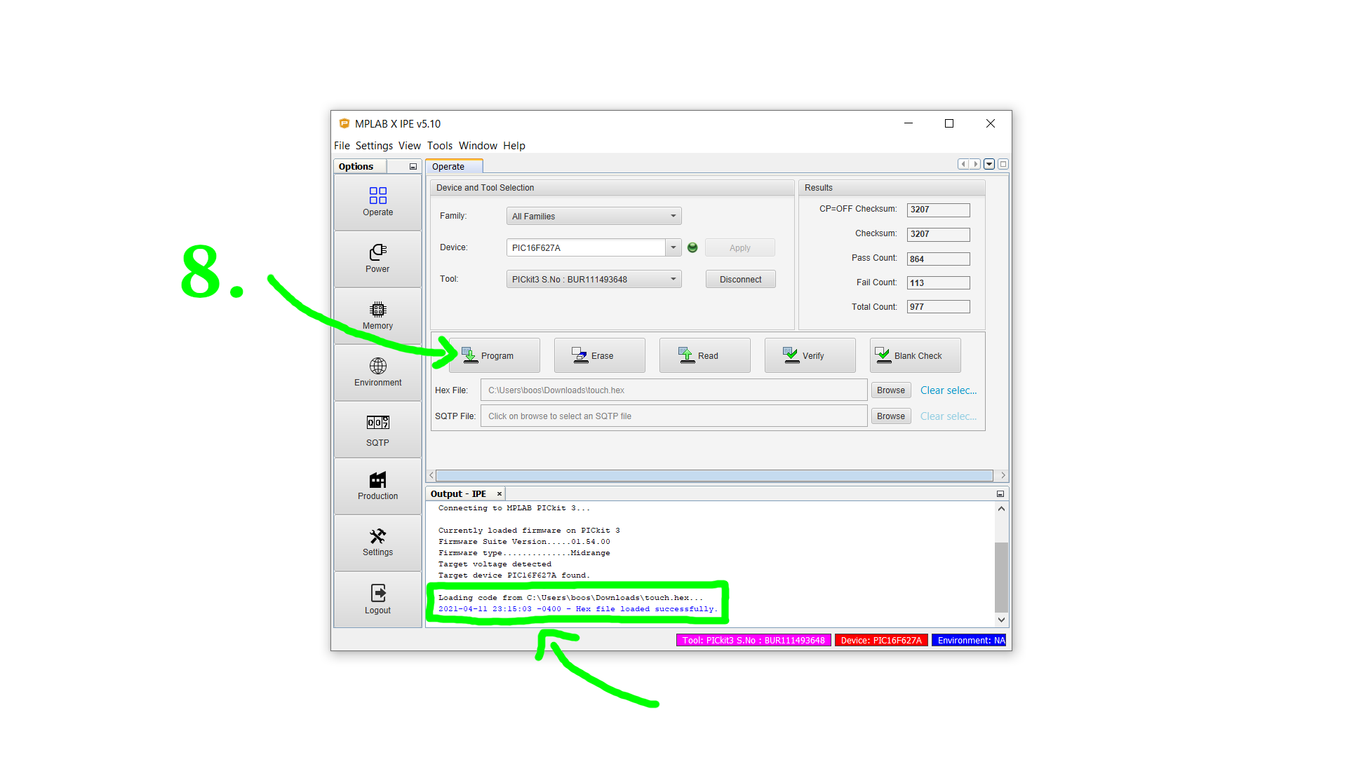
At the bottom output prompt it should now say “Target device PIC16F627A found.” Next, click on Browse to select the touch.hex file (which you can download in the resources box or create yourself by compiling the source code).

After the file has been loaded successfully (check the bottom output prompt) you can click on Program.
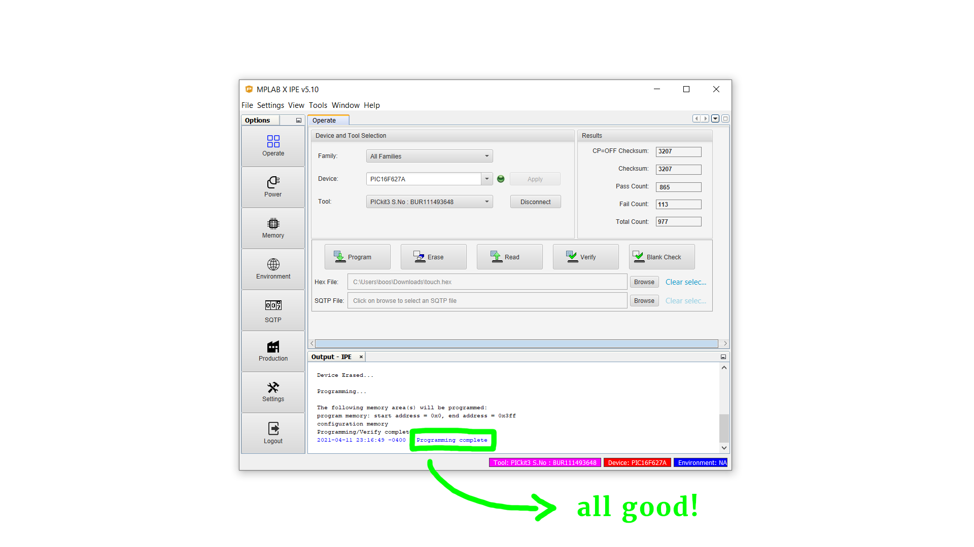
Our .hex file is now being transferred to the PIC16F627A. After a few seconds it should say “Programming complete.”
Now you can disconnect the PICkit3 from the circuit and your computer. Also briefly disconnect the batteries and then reconnect them, so that the PIC16F627A gets reset and runs the calibration procedure for our touch sensors. If you don't do that then the buttons 1 and 2 won't work reliably because they were previously connected to the PICkit3, which changed the value for their discharge times.
But then it should all work, and you can test out your brand new touch sensor!
But what if it doesn't work? There are many things that can go wrong, but here are some ideas:
- Make sure you inserted all components correctly (the LEDs have a polarity, and the electrolytic capacitor C1 has polarity as well).
- Make sure the power rails on both sides of the breadboard are connected together (plus to plus, minus to minus).
- Play around with the threshold values
thr1,thr2,thr3, andthr4. I set them all to 10 in the code example, and that works well for me, but your conditions might be different :)
And if it still doesn't work, there could be another reason: earth itself! What do I mean by that?
When I built the circuit, sometimes it just would not work reliably. I had to connect the ground rail to a big chunk of metal, otherwise known as “protective earth.” That is the funny looking symbol in the schematic that I mentioned earlier:

Without going to deep: in an ideal world, the ordinary ground symbol means a potential of exactly zero volt (0V). But for small battery-operated circuits like the one we have here that assumption is not always justified. A small amount of stray charges, if they have no place to go, especially in the presence of our large 10MΩ resistors, can create small voltages that shift the ground potential to a non-zero value. And that will mess with the circuit. If we add a physical earth connection then the circuit is no longer an isolated system but is in touch with a much larger ground potential, and these annoying little charges that make our life hard can dissipate :)
So you could just use an alligator clip and connect the ground rail to a big chunk of metal, and yes, that actually works, but you could also just run the circuit from a regular power supply (instead of a battery), and that works just as well.
YouTube videos
I covered this entire tutorial in a dedicated YouTube video:
And I also made a separate video about the C source code:
Final thoughts
I love these little touch switches because they are so simple to build. There are a few pitfalls when you want to build this yourself, but I think the end result really is worth it.
If you have built this circuit then make sure to share it with me on social media, I always enjoy seeing your creations. And if it just won't work, you can of course also reach out to me so that we can figure out what's wrong.
I will most likely use these touch switches in a future project, and I just love how they work so nicely on breadboards without additional capacitors. That also means that if you want to build this circuit on a PCB you probably need to add a few picofarads of actual capacity to make it work.
Thank you so much for your interest, thank you for reading this article, and have a wonderful day!
Appendix: The full source code
Here you can find the full source code. The code (as well as the .hex file) are also available for download in the resources box.
/*
 * File:   main.c
 * Author: boos
 *
 * Created on March 13, 2021, 12:50 PM
 */

// CONFIG
#pragma config FOSC = INTOSCIO  // Oscillator Selection bits (INTOSC oscillator: I/O function on RA6/OSC2/CLKOUT pin, I/O function on RA7/OSC1/CLKIN)
#pragma config WDTE = OFF       // Watchdog Timer Enable bit (WDT disabled)
#pragma config PWRTE = OFF      // Power-up Timer Enable bit (PWRT disabled)
#pragma config MCLRE = OFF      // RA5/MCLR/VPP Pin Function Select bit (RA5/MCLR/VPP pin function is digital input, MCLR internally tied to VDD)
#pragma config BOREN = ON       // Brown-out Detect Enable bit (BOD enabled)
#pragma config LVP = OFF        // Low-Voltage Programming Enable bit (RB4/PGM pin has digital I/O function, HV on MCLR must be used for programming)
#pragma config CPD = OFF        // Data EE Memory Code Protection bit (Data memory code protection off)
#pragma config CP = OFF         // Flash Program Memory Code Protection bit (Code protection off)

#include <xc.h>


// where are our LEDs?
#define LED1 RB0
#define LED2 RB1
#define LED3 RB2
#define LED4 RB3

// where are our buttons?
#define SW1 RB7
#define SW2 RB6
#define SW3 RB5
#define SW4 RB4

// shortcuts for tristate registers of the buttons
#define TRIS1 TRISB7
#define TRIS2 TRISB6
#define TRIS3 TRISB5
#define TRIS4 TRISB4


// auxiliary function, see below
void wait (void);


// variables
int time;
int avg1, avg2, avg3, avg4;
char thr1, thr2, thr3, thr4;
int buf1, buf2, buf3, buf4;

// you can adjust the PWM brightness levels here
char pwm_values[] = {0, 20, 100, 255};
char pwm = 0, pwmlevels = 4;


// main function
void main (void) {


    // set the entire PORTB as an output on startup
    TRISB = 0;


    // calibrate all buttons
    // (find average discharge times)
    for (char c=0; c<16; c++) {

        avg1=0; time=0;
        TRIS1 = 0; SW1 = 1; wait(); TRIS1 = 1; while (SW1==1) { time++; }
        avg1 += time / 16;

        avg2=0; time=0;
        TRIS2 = 0; SW2 = 1; wait(); TRIS2 = 1; while (SW2==1) { time++; }
        avg2 += time / 16;

        avg3=0; time=0;
        TRIS3 = 0; SW3 = 1; wait(); TRIS3 = 1; while (SW3==1) { time++; }
        avg3 += time / 16;

        avg4=0; time=0;
        TRIS4 = 0; SW4 = 1; wait(); TRIS4 = 1; while (SW4==1) { time++; }
        avg4 += time / 16;

    }

    // set threshold values (play around with these values to make it work for you)
    thr1 = 15; thr2 = 15; thr3 = 15; thr4 = 15;


    // configure PWM module, frequency: 3.9kHz, resolution: 10bit
    // (more details at www.friendlywire.com/tutorials/pwm)

    // PWM resolution: 10 bit
    PR2 = 0xff;

    // turn on timer 2 and set its prescaler to 1:1
	T2CON = 0b100;

    // turn on PWM module
	CCP1CON = 0b1100;

    // set startup duty cycle value to first entry in our custom PWM array
	CCPR1L = pwm_values[pwm];


    // main loop
    while (1) {


        // momentary mode
        time = 0; TRIS1 = 0; SW1 = 1; wait(); TRIS1 = 1; while (SW1==1) { time++; }
        if (time-avg1 > thr1) {
            buf1 = 20;
            LED1 = 1;
        } else {
            if (buf1 > 0) {
                buf1--;
            } else {
                LED1 = 0;
            }
        }


        // toggle mode
        time = 0; TRIS2 = 0; SW2 = 1; wait(); TRIS2 = 1; while (SW2==1) { time++; }
        if (time-avg2 > thr2) {
            if (buf2 == 0) {
                LED2 = ~ LED2;
            }
            buf2 = 20;
        } else if (buf2 > 0) {
            buf2--;
        }


        // timer mode (adjust duration with variable "buf3")
        time = 0; TRIS3 = 0; SW3 = 1; wait(); TRIS3 = 1; while (SW3==1) { time++; }
        if (time-avg3 > thr3) {
            buf3 = 500;
            LED3 = 1;
        } else {
            if (buf3 > 0) {
                buf3--;
            } else {
                LED3 = 0;
            }
        }


        // dimmer mode (adjust dimming values in the array "pwm_values")
        time = 0; TRIS4 = 0; SW4 = 1; wait(); TRIS4 = 1; while (SW4==1) { time++; }
        if (time-avg4 > thr4) {
            if (buf4 == 0) {
                pwm++;
                if (pwm >= pwmlevels) {
                    pwm = 0;
                }
                CCPR1L = pwm_values[pwm];
            }
            buf4 = 20;
        } else if (buf4 > 0) {
            buf4--;
        }


    }

}

// this function waits for eight cycles and does nothing
// (we need this so the stray capacity can charge up enough)
void wait (void) {

    NOP(); NOP(); NOP(); NOP();
    NOP(); NOP(); NOP(); NOP();

}